Manufacturing method of rare earth-doped optical fiber preformed rod
A technology of optical fiber preform and manufacturing method, which is applied in the direction of manufacturing tools and glass manufacturing equipment, etc. It can solve the problems of small diameter of the core area of the optical fiber preform, high requirements for heat preservation and high temperature resistance, and lack of large-scale production. The effect of large size, reducing the requirements for temperature resistance and corrosion resistance, and improving production efficiency
- Summary
- Abstract
- Description
- Claims
- Application Information
AI Technical Summary
Problems solved by technology
Method used
Image
Examples
no. 1 example
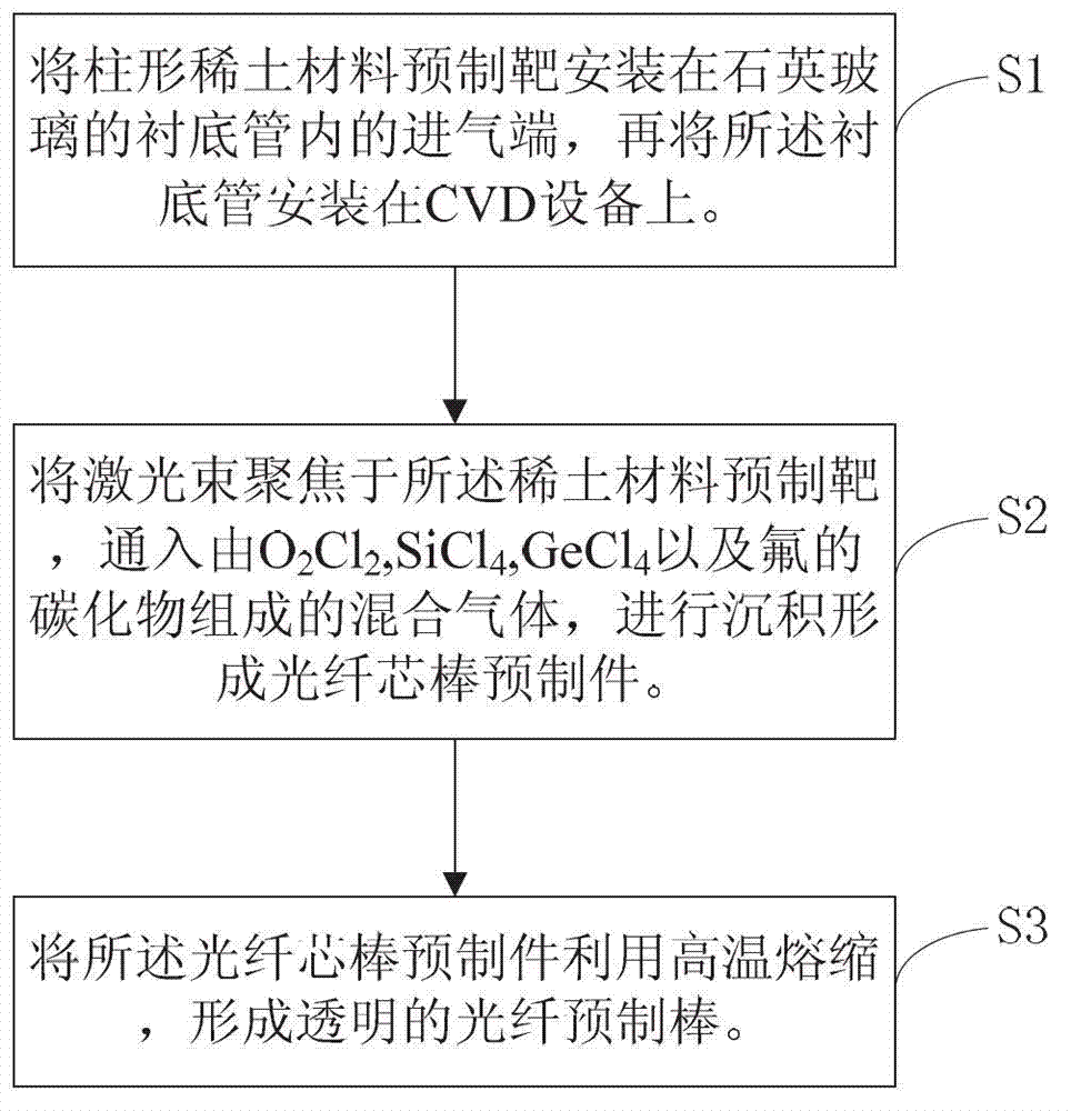
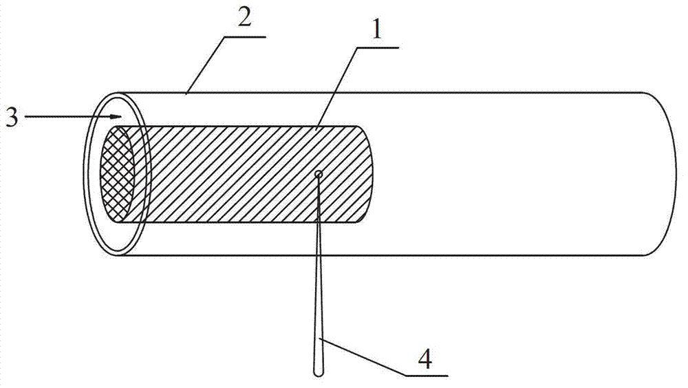
[0040] Such as figure 2 As shown, the rare earth material prefabricated target rod 1 is installed on the inner inlet end of the substrate tube 2 of quartz glass and fixed, the inner diameter of the substrate tube 2 is 15 mm, the diameter of the rare earth material prefabricated target rod 1 is 8 mm, and the rare earth material is YbCl 3 (ytterbium chloride), AlCl 3 Mixture, rare earth material prefabricated target rod 1 with a length of 100 mm and a density of 3.5 g / cm 3 , installing the assembled substrate tube 2 on the MCVD equipment. Then focus the laser 4 with a wavelength of 1064nm on the surface of the prefabricated rare earth material target rod 1. The diameter of the beam spot of the laser 4 is 4.5mm, and the laser output power is 100w. material, during the above laser ablation evaporation process, at the same time, the O 2 , Cl 2 、SiCl 4 、GeCl 4 And the mixed gas 3 that the carbide of fluorine is formed, the carbide of fluorine is C in the present embodiment 2...
no. 2 example
[0042] Such as figure 2 As shown, the rare earth material prefabricated target rod 1 is installed and fixed at the inner inlet end of the substrate tube 2 of quartz glass, the inner diameter of the substrate tube 2 is 24 mm, the diameter of the rare earth material prefabricated target rod 1 is 15 mm, and the rare earth material is ErCl 3 (erbium chloride), AlCl 3 Mixture, rare earth material prefabricated target rod 1 with a length of 100mm and a density of 4g / cm 3 , installing the assembled substrate tube 2 on the PCVD equipment. Then focus the laser 4 with a wavelength of 800nm on the surface of the prefabricated rare earth material target rod 1. The beam spot diameter of the laser 4 is 4mm, and the laser output power is 200w. , during the above laser ablation evaporation process, at the same time, O is introduced in the direction of the arrow 2 , Cl 2 、SiCl 4 、GeCl 4 And the mixed gas 3 that the carbide of fluorine is formed, the carbide of fluorine is C in the pre...
no. 3 example
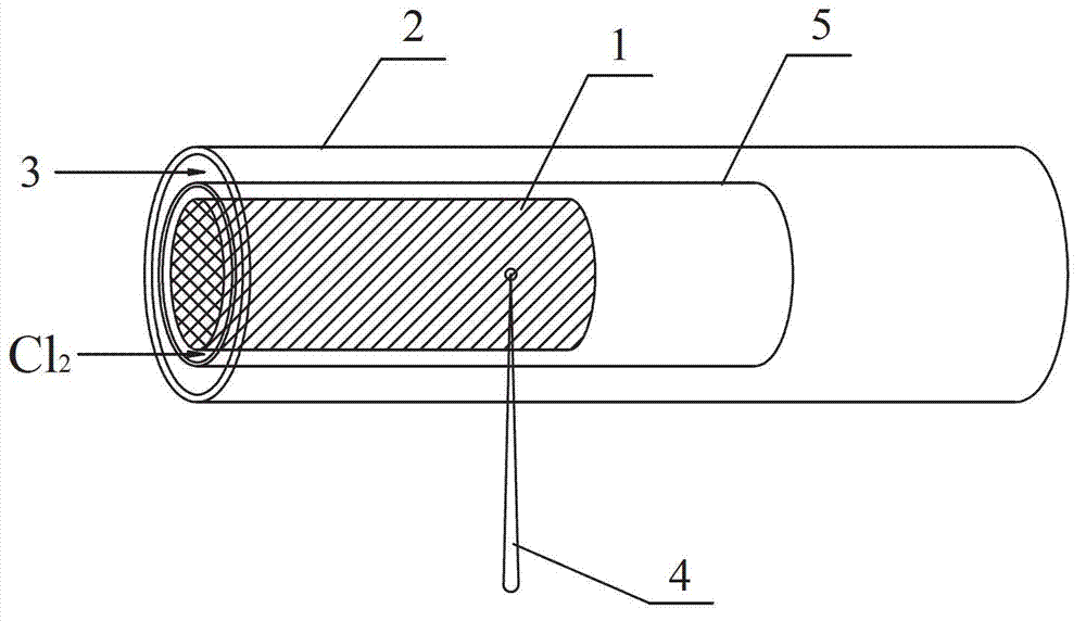
[0044] Such as image 3 As shown, the rare earth material prefabricated target rod 1 is first installed inside the quartz glass protective tube 5, and then the quartz glass protective tube 5 is installed and fixed at the inlet end of the substrate tube 2. The inner diameter of the substrate tube 2 is 51mm, and the rare earth material The diameter of the prefabricated target rod 1 is 18mm, and the rare earth material is YbCl 3 , ErCl 3 , AlCl 3 Mixture, rare earth material prefabricated target rod 1 with a length of 100mm and a density of 4g / cm 3 , installing the assembled substrate tube 2 on the PCVD equipment. Then focus the laser 4 with a wavelength of 1300nm on the surface of the prefabricated rare earth material target rod 1. The beam spot diameter of the laser 4 is 4mm, and the laser output power is 200w. , during the above laser ablation evaporation process, at the same time, O is introduced in the direction of the arrow 2 , Cl 2 、SiCl 4 、GeCl 4 And the mixed gas...
PUM
 Abstract
Description
Claims
Application Information
 - R&D
- Intellectual Property
- Life Sciences
- Materials
- Tech Scout
- Unparalleled Data Quality
- Higher Quality Content
- 60% Fewer Hallucinations
Browse by: Latest US Patents, China's latest patents, Technical Efficacy Thesaurus, Application Domain, Technology Topic, Popular Technical Reports.
© 2025 PatSnap. All rights reserved.Legal|Privacy policy|Modern Slavery Act Transparency Statement|Sitemap|About US| Contact US: help@patsnap.com


