Automatic welding experiment system for simulating medium pressure liquid or gaseous environment

A technology of automatic welding and gas environment, applied in welding equipment, metal processing equipment, manufacturing tools, etc., can solve the problems of low automation, high experiment cost, poor applicability, etc., achieve high automation, good applicability, and reduce experiment cost effect

Inactive Publication Date: 2014-08-13
HARBIN INST OF TECH
View PDF8 Cites 0 Cited by
  • Summary
  • Abstract
  • Description
  • Claims
  • Application Information

AI Technical Summary

Problems solved by technology

[0003] The purpose of the present invention is to provide an automatic welding test system for simulating a medium-pressure liquid or gas environment in order to solve the problems of low automation, poor applicability and high test cost of the existing welding test system for simulating a pressure environment

Method used


Image

  • Automatic welding experiment system for simulating medium pressure liquid or gaseous environment
  • Automatic welding experiment system for simulating medium pressure liquid or gaseous environment
  • Automatic welding experiment system for simulating medium pressure liquid or gaseous environment

Examples


specific Embodiment approach 1

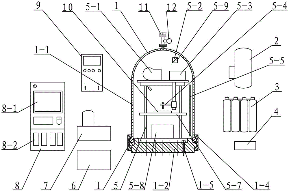
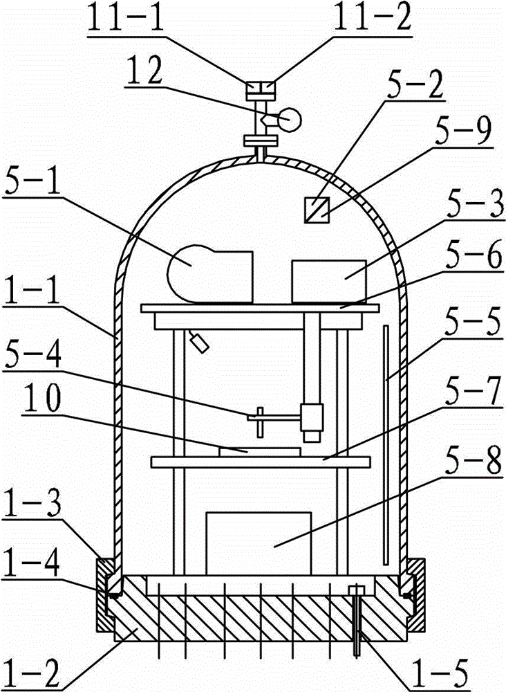
[0014] Specific implementation mode one: combine Figure 1 ~ Figure 3 Describe this embodiment, this embodiment includes a medium pressure environment simulation cabin 1, a gas recovery device 2, a gas cylinder bundle 3, a vacuum pump 4, an experimental equipment 5 in the cabin, a cooling water circulation pump 6, a hydraulic pump station 7, a control cabinet 8 and a welding Power supply 9, safety valve 11 and pressure gauge 10, medium pressure environment simulation cabin 1 includes cabin body 1-1, bilge 1-2, annular sealing ring 1-3, two clamp devices 1-4 and several cabin penetrations Connectors 1-5, several tank penetration connectors 1-5 are evenly arranged in the end surface of the bilge 1-2, the cabin body 1-1 is set above the bilge 1-2, and the annular sealing ring 1-3 is set in the tank Between the body 1-1 and the bilge 1-2, two hoop devices 1-4 are arranged symmetrically at the junction of the cabin body 1-1 and the bilge 1-2, and the two hoops 1-4 are fastened into...

specific Embodiment approach 2

[0015] Specific implementation mode two: combination Figure 4 Describe this embodiment, each clamp device 1-4 of this embodiment is composed of semicircular clamp 1-4-1, clamp opening and closing cylinder 1-4-2, clamp support wheel 1-4-3, cylinder connector 1-4-4 and the oil cylinder bracket 1-4-5, the curved inner surface of the semicircular clamp 1-4-1 is provided with a trapezoidal groove 1-4-1-1 along the length direction, and the clamp opening and closing cylinder 1- The fixed end of 4-2 is hinged with the cylinder bracket 1-4-5, the piston end of the clamp opening and closing cylinder 1-4-2 is hinged with the cylinder connector 1-4-4, and the cylinder connector 1-4-4 is connected with the semicircle The arc-shaped outer surface of the clamp 1-4-1 is fixedly connected, and the clamp support wheel 1-4-3 is installed on the lower end surface of the semicircular clamp 1-4-1. During use, the oil cylinder support 1-4-5 is fixedly connected with the upper end surface of the p...


PUM


Abstract

The invention discloses an automatic welding experiment system for simulating a medium pressure liquid or gaseous environment, and relates to an underwater welding system, in order to solve the problems of low automation degree, poor applicability and high experiment cost of the existing welding experiment system for simulating a pressure environment. An industrial personal computer is respectively connected with a pressure sensor, a liquid level sensor, a temperature sensor and a programmable logic controller (PLC) module through a signal cable; the PLC module is respectively connected with a gas recovering device, a gas bottle bundle, a vacuum pump, a welding power supply, a cooling water circulating pump, a hydraulic pump station, a wire feeding machine, a pressure sensor, a servo motor set, a welding gun, a liquid level sensor, an upper two-dimensional motion platform, a lower two-dimensional motion platform, a cabin smoke dust filtering device and a temperature sensor through a signal cable; the gas recovering device, the gas bottle bundle, the vacuum pump and the cooling water circulating pump are respectively connected with a cabin body through pipelines; the hydraulic pump station is connected with a cylinder on a loop device through a pipeline; and the welding power supply is connected with the welding gun through a lead wire. The welding experiment system is used for simulating the underwater welding.

Description

technical field [0001] The invention relates to an underwater welding system, in particular to a welding experiment system for simulating a medium-pressure liquid or gas environment. Background technique [0002] With the development of marine resources, a large number of steel structures are used in marine engineering, such as submarine oil pipelines, offshore drilling platforms, and sea-crossing bridges. Whether it is the construction of structures or the maintenance of facilities, underwater welding is required. Whether it is the construction of structures or the maintenance of facilities, underwater welding technology has irreplaceable advantages. Underwater wet welding can be applied to pressure environments where the water depth does not exceed 100 meters; when the water depth exceeds 100 meters, underwater high-pressure dry welding is generally used. Regardless of underwater wet or high-pressure dry welding, welding is carried out in an environment higher than 1 atm...

Claims


Application Information

Patent Timeline
Patent Type & Authority Patents(China)
IPC IPC(8): B23K31/02
Inventor 高洪明李海超李凯巩杉陈弈
Owner HARBIN INST OF TECH
Why Eureka
Try Eureka