
Method, device, program, and computer readable recording medium for failure analysis of spot welded section

一种分析方法、点焊的技术,应用在分析材料、测量装置、焊接设备等方向,能够解决花费制作成本、未达到稳定纵弯曲形态、断裂等问题,达到研究容易的效果

Active Publication Date: 2012-12-12
NIPPON STEEL CORP
View PDF9 Cites 11 Cited by
  • Summary
  • Abstract
  • Description
  • Claims
  • Application Information

AI Technical Summary

Problems solved by technology

[0004] Regarding the spot welding of components, in order to stabilize the longitudinal bending, if the spot welding interval, welding spot diameter, and welding conditions are not optimized, there is a problem that fractures from the welding point will occur during longitudinal bending, and a stable longitudinal bending will not be achieved. Curved form, resulting in reduced absorption of impact energy
[0006] However, this method requires trial and error, such as trial production and testing for each vehicle and each part.
Therefore, there is a problem that production costs are incurred and design also takes time

Method used


Image

  • Method, device, program, and computer readable recording medium for failure analysis of spot welded section
  • Method, device, program, and computer readable recording medium for failure analysis of spot welded section
  • Method, device, program, and computer readable recording medium for failure analysis of spot welded section

Examples


Embodiment 1

[0118] In Table 3, the experimental conditions and experimental results of Example 1 are shown.

[0119] [table 3]

[0120]

[0121] exist Figure 8 And Table 4 shows the analysis conditions and analysis results of Example 1. In Invention Examples 1 to 7, the fracture mode is load-type fracture, and the error of the fracture load is -2.6%, which is relatively small. In Table 3, the load-type fracture occurred in the experiment, so it is ideal to use the load-type fracture method for analysis as in Invention Examples 1 to 7, but in analysis, the deformation is advancing and the force or moment applied to the welded part is in the Therefore, fracture prediction can be performed in a method other than the load-based fracture method. Inventive examples 8 to 10 are the fracture judgment results of the torque type fracture mode, and inventive examples 11 to 13 are the fracture judgment results of the internal solder joint fracture mode. As shown in Table 4, the accuracy of th...

Embodiment 2

[0125] In Table 5, the experimental conditions and experimental results of Example 2 are shown. In Inventive Example 1 and Comparative Example 2, the fracture mode was load fracture.

[0126] [table 5]

[0127]

[0128] When it is Invention Example 1, such as Figure 9A , Figure 9B As shown, the fractured part of the spot weld and the deformed shape of the test body are in good agreement with the experiment. On the other hand, in Comparative Example 2, the allowable load value at each moment after reaching the maximum allowable load value of the welded portion is not obtained, and the allowable load value becomes 0 immediately after reaching the maximum allowable load value. In this case, it was found that the interlocking spot welds fractured and fractures occurred in all the spot welds of the hat test body, which was inconsistent with the experimental results.

Embodiment 3

[0130] The experimental conditions of Example 3 are shown in Table 6.

[0131] [Table 6]

[0132]

[0133] The main dimensions of the test bodies used in Example 3 are shown below.

[0134] Cap: The straight line at the bottom of the cap is 45mm, the width of the flange is 20mm, the height of the section is 43mm, and the overall length is 370mm

[0135] Flat plate: width 100mm, length 360mm

[0136] Spot welding interval: 40mm

[0137] The test conditions of Example 3 are shown below.

[0138] Drop hammer shaft crush test: drop hammer weight 140kg, initial velocity 36km / h

[0139] In either example, the effective width was 20 mm of the flange width to the cap side member, and 50 mm, which is half the width, to the flat plate. As a result of the test, plug welding fractures occurred at two points.

[0140] exist Figure 10 And Table 7 shows the analysis conditions and analysis results of Example 3. As shown in Example 1, in the test in which the cross-sectional shape ...


PUM


Abstract

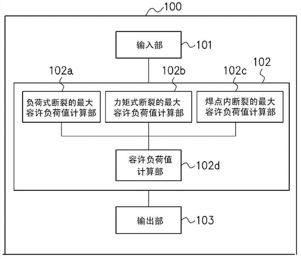
The maximum allowable load value of a welded section for each of the fracture modes of load fracture, moment fracture, and nugget interior fracture is calculated on the basis of at least one from among the thickness (t), the tensile strength (TS), the elongation (El), the nugget chemical components, the welded section nugget diameter (d), the effective width (B) determined by the distance to a welded section, edge, or ridge line adjacent the welded section, and the cross section height (H) of respective spot-welded steel plates. In addition, in accordance with the fracture modes, the hourly allowable load value after reaching the maximum allowable load value of the welded section is calculated, and a fracture limit requiring the displacement or time at which said allowable load value becomes 0, in other words, at which a complete fracture occurs, is calculated.

Description

technical field [0001] The present invention relates to a method, device, program, and computer-readable recording medium for analyzing fractures of spot welds in automobile collision simulations and the like. Background technique [0002] In recent years, in the automobile industry, the development of a vehicle body structure capable of reducing damage to occupants during a collision has become an urgent issue. Such a vehicle body structure with high crash safety can be realized by absorbing impact energy at the time of a collision with structural members other than the passenger compartment, minimizing deformation of the passenger compartment and securing a living space. That is, it is important to absorb impact energy by structural components. [0003] The main structural component that absorbs the impact energy of a car in a frontal full-contact collision (フルッット collision) or a partial collision (フセット collision) is the front side member. After the front side member is ...

Claims


Application Information

Patent Timeline
Patent Type & Authority Applications(China)
IPC IPC(8): G01N3/00
CPCG01N3/00G01N2203/0212Y02T10/82B23K31/125G01N2203/0296B23K11/11
Inventor 吉田博司野村成彦上西朗弘
Owner NIPPON STEEL CORP
Learn More