
Camber surface wave transmission and bidirectional reception focusing ultrasonic imaging new method

An ultrasonic imaging, receiving and focusing technology, applied in echo tomography and other directions, can solve the problems of inability to meet the needs of clinical diagnosis and medical scientific research, large ultrasonic dose, low time and space resolution of ultrasonic imaging technology, etc. Practicality, slow overcoming speed, huge social and economic benefits

Active Publication Date: 2012-12-05
曹铁生 +1
View PDF5 Cites 2 Cited by
  • Summary
  • Abstract
  • Description
  • Claims
  • Application Information

AI Technical Summary

Problems solved by technology

However, the traditional ultrasound imaging technology still has many defects, and it is far from meeting the needs of clinical diagnosis and medical scientific research.
For example, the ultrasonic imaging technology of the traditional single-point image information acquisition method has low temporal and spatial resolution, and the emitted ultrasonic dose is relatively large, etc.
In addition, the problem of thickness artifacts (ie volume effect) of traditional ultrasound has always existed
However, even so, until now, there is no ultrasound imaging technique that can completely eliminate thickness artifacts worldwide

Method used


Image

  • Camber surface wave transmission and bidirectional reception focusing ultrasonic imaging new method
  • Camber surface wave transmission and bidirectional reception focusing ultrasonic imaging new method

Examples


Embodiment Construction

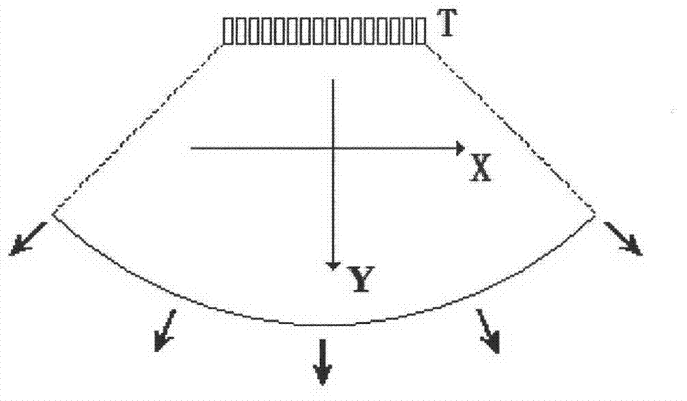
[0008]In order to realize the core technical requirements of the patent of the present invention, the specific implementation methods are as follows: (1) Probe aspect: Since there are already finished products of matrix probes on the market, they can be directly selected. The department where the applicant of this patent works has a matrix sector-scanning probe produced by GE Company that has divisions in the thickness direction. The company uses 8 rows (8*128=1024) matrix probes, which meet the requirements of this patent. In addition, according to the requirements of this patent, it is also possible to study probes with 16 rows or other layer thicknesses, compare the differences between each probe, and select the most suitable probe structure, so that this patent can achieve the most ideal effect. (2) Focusing in the thickness direction: The thickness direction focusing requirements involved in this patent, the matrix probe is used to use the currently quite mature electroni...


PUM


Abstract

The invention discloses a camber surface wave transmission and bidirectional reception focusing ultrasonic imaging new method, which aims to overcome the defects of slow speed, large transmitting dosage and low resolution of the conventional ultrasonic imaging, eliminates the problem of thickness artifact generally exiting in the conventional ultrasonic imaging and belongs to a technical breakthrough in the field of medical ultrasonic imaging. The technical core is that camber surface wave is transmitted in the lateral direction by using an electronic phased array matrix probe by controlling time delay of ultrasonic wave transmitted by each array element, and meanwhile, transmission focusing is performed in the thickness direction, so that a focusing region is positioned at a part which is 1 / 2 the maximum investigation depth; after transmission, dynamic reception focusing in lateral direction and thickness direction is performed on each determined sound wave of a pixel back-scatter probe on a camber surface in the thickness direction from shallow to deep respectively; and pixel information of each layer is acquired and stored for imaging. Through the method, the defects of the conventional ultrasonic imaging can be overcome, the thickness artifact is eliminated, the quality of two-dimensional ultrasonic imaging is greatly improved, and important theoretical significance and practical significance are realized.

Description

Technical field [0001] The patent of the invention relates to a new medical ultrasound imaging method, the purpose of which is to break through the bottleneck of traditional ultrasound imaging, eliminate thickness artifacts, and greatly improve image quality. The invention patent belongs to an important technological breakthrough in the field of medical ultrasound imaging. Background technique [0002] Medical ultrasound imaging technology refers to the use of ultrasonic energy emitted to human tissue, according to the sound energy information scattered back to the probe inside the human tissue, to extract the section or three-dimensional structure image of the internal organs of the human body, which provides extremely important information for clinical diagnosis and treatment of diseases and medical research. Human anatomy and function information. At present, ultrasound imaging technology has become an indispensable and important part of modern medical imaging, and has b...

Claims


Application Information

Patent Timeline
IPC IPC(8): A61B8/14
Inventor 曹铁生王臻
Owner 曹铁生
Learn More