
Equipment and method for manufacturing solar cell positive electrode

A technology of solar cells and front electrodes, applied in circuits, photovoltaic power generation, electrical components, etc., can solve the problems of silver paste consumption, large shading area, thin grid line width, etc., to reduce production costs, improve conversion efficiency, reduce The Effect of Grid Width

Inactive Publication Date: 2012-11-28
HANGZHOU SILARS TECH
View PDF3 Cites 7 Cited by
  • Summary
  • Abstract
  • Description
  • Claims
  • Application Information

AI Technical Summary

Problems solved by technology

However, the screen printing process is facing great difficulties and severe challenges in reducing the width of the fine grid line of the front electrode of the battery.
On the other hand, since screen printing uses silver paste to pass through the screen and is printed on the battery sheet to form fine grid lines, it will consume more silver paste than using conductive wire to wrap silver paste, thus inevitably increasing the Cost of production
Therefore, the disadvantages of making the front electrode of the solar cell by the screen printing machine are: higher manufacturing cost, wider thin grid line, large shading area, low photoelectric conversion efficiency of the battery, etc., and the solar cell sheet made by the equipment and method of the present invention saves cost at least 20%-30%

Method used


Image

  • Equipment and method for manufacturing solar cell positive electrode
  • Equipment and method for manufacturing solar cell positive electrode
  • Equipment and method for manufacturing solar cell positive electrode

Examples


Embodiment Construction

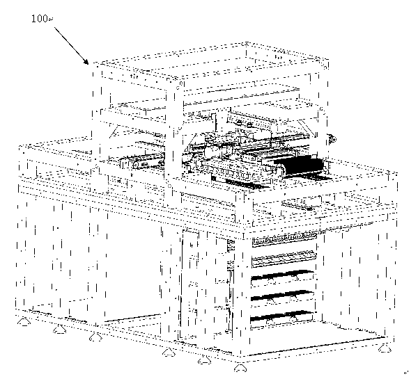
[0053] The present invention adopts a solar cell front electrode manufacturing equipment completely different from the prior art. In the prior art, fine grid lines are printed on the cell through a screen on a screen printing machine. The improvement of the prior art is also to Improvements to screen printing machines, or improvements to conductive pastes. The invention adopts very effective alternative equipment and manufacturing method to replace the screen printing machine and the screen printing process, so that the manufacturing cost is reduced and the photoelectric conversion efficiency of the solar cell is further improved.

[0054] Embodiments of the present invention are described in detail below in conjunction with the accompanying drawings:

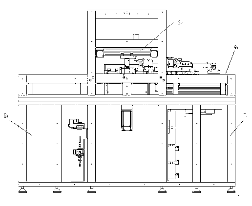
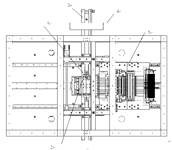
[0055] like Figure 1 to Figure 2 As shown, it shows an embodiment of a new solar cell front electrode manufacturing equipment. The manufacturing equipment 100 mainly includes a frame 9, a wire feeding mechanism 10, a coating ...


PUM


Abstract

The invention discloses equipment and a method for manufacturing a solar cell positive electrode. The manufacturing equipment comprises a frame, a wire feeding mechanism, a wire drawing mechanism, a paste coating mechanism and a wire attachment mechanism, wherein the wire feeding mechanism provides a conductive wire; the wire drawing mechanism draws the conductive wire out of the wire feeding mechanism so as to penetrate through the paste coating mechanism; the paste coating mechanism is used for coating the conductive wire on conductive paste; and the wire attachment mechanism attaches the conductive wire coated with the paste to the positive side of the solar cell, so that the manufacture of the cell positive electrode is finished. The invention also discloses a method for manufacturing the cell positive electrode. The method comprises the following steps of: wire drawing, paste coating, wire attachment, wire cutting and wire head processing. The manufacturing equipment and method have the beneficial effects that according to the cell positive electrode manufactured by the equipment and method, the diameter of the conductive wire and the paste coating mechanism are adjusted, so that the width of the grid line can be effectively reduced, the height-width ratio of the positive electrode is improved, the manufacturing cost is reduced, and the conversion efficiency is improved.

Description

technical field [0001] The invention relates to the field of manufacturing a front electrode of a solar cell, in particular to a manufacturing device and a manufacturing method of a front electrode of a solar cell. Background technique [0002] At present, the manufacturing equipment for the front electrode of solar cells is mainly a screen printing machine. A general screen printing machine has: a printing mounting table, a printing mask, and a scraper; the printing mounting table has a plurality of adsorption holes on the mounting table. Vacuum suction is used to support and fix the printed matter placed on the mounting table; the printing mask is used to form a prescribed electrode pattern on the printed matter supported and fixed on the printing mounting table; The conductive paste on the printing mask applies a predetermined pressure to print on the object to be printed. [0003] The characteristics of the above-mentioned traditional screen printing process for making ...

Claims


Application Information

Patent Timeline
IPC IPC(8): H01L31/18H01L31/0224
CPCB41F15/0804H01L31/18H01L31/188H01L31/0224H01L31/022425B41F15/0881B41F15/36B41P2215/50Y02E10/50
Inventor 武建康秋晨武宇涛马勇王磊
Owner HANGZHOU SILARS TECH
Learn More