
Medium-and-low-temperature waste-heat utilization cooling/power combination system

A technology of low-temperature waste heat and regenerator, applied in energy-saving heating/cooling, refrigerators, energy industry, etc., can solve the problems of low energy utilization, unsatisfactory users, and energy waste, so as to improve energy utilization rate and reduce replacement Thermal temperature difference, the effect of reducing energy loss

Active Publication Date: 2012-11-28
XI AN JIAOTONG UNIV
View PDF5 Cites 13 Cited by
  • Summary
  • Abstract
  • Description
  • Claims
  • Application Information

AI Technical Summary

Problems solved by technology

[0002] In the industrial process, such as the production of industrial products such as cement and glass and the power generation process of power plants, a large amount of waste heat resources are discharged into the environment in various forms, which not only aggravates the urban "heat island effect" and causes serious environmental thermal pollution. At the same time, it also causes a waste of energy, which is the main reason for the low energy utilization.
The traditional recovery of industrial waste heat widely adopts organic Rankine cycle system and Karina cycle system. However, the traditional waste heat recovery cycle can only output power work or electric energy, and cannot output power and cooling capacity at the same time, which cannot meet the various needs of users. need

Method used


Image

  • Medium-and-low-temperature waste-heat utilization cooling/power combination system

Examples


Embodiment Construction

[0014] The present invention will be described in further detail below in conjunction with the accompanying drawings.

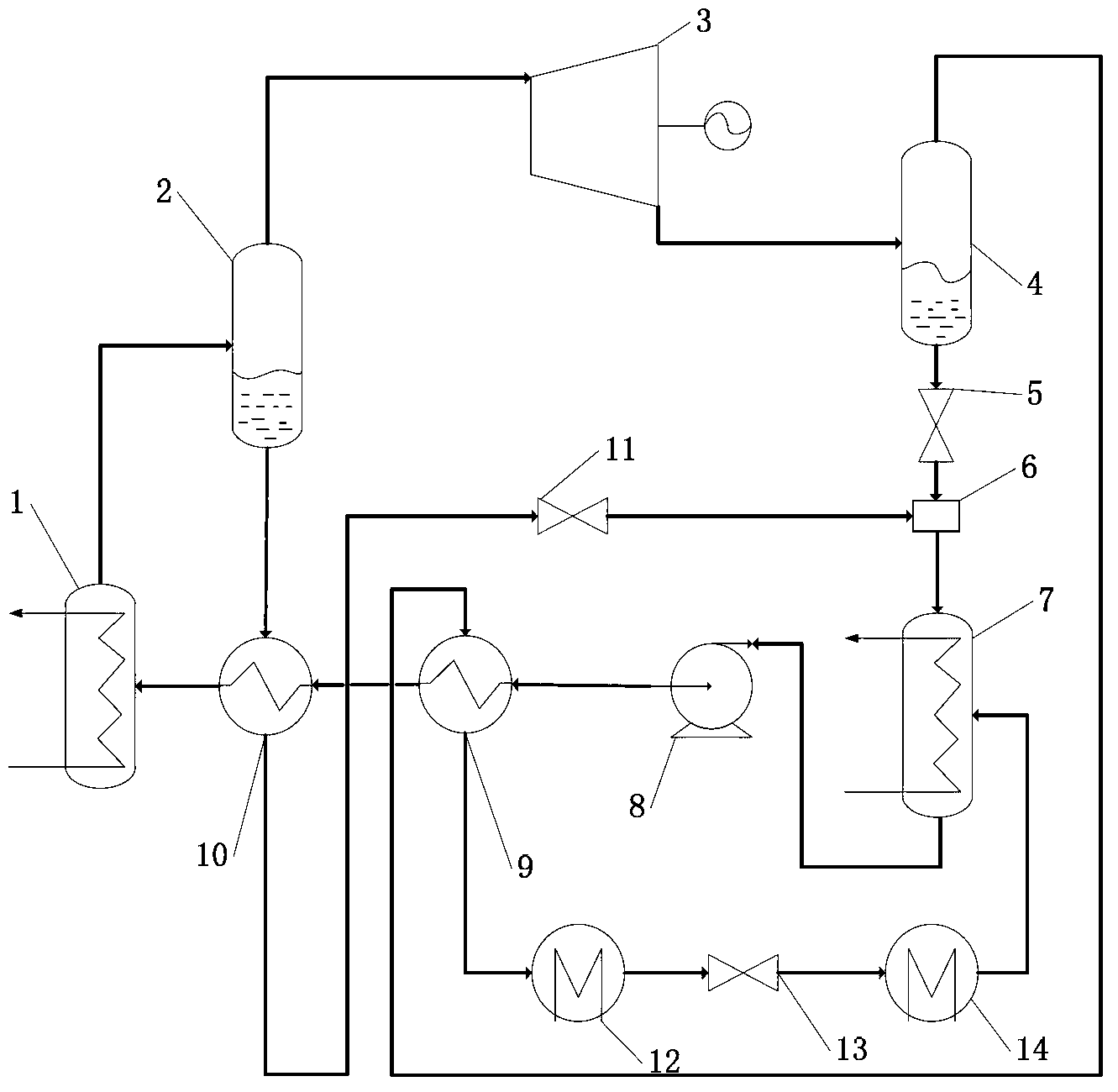
[0015] see figure 1 , the present invention includes a steam generator 1 and a first-stage gas-liquid separator 2 connected to the steam generator 1, the liquid outlet of the first-stage gas-liquid separator 2 passes through the second throttle valve 11, the mixing The device 6 is connected with the feed inlet of the absorber 7; the steam outlet of the first-stage gas-liquid separator 2 is connected with the second-stage gas-liquid separator 4 through an expander 3 externally connected with an output power load; The liquid outlet of the second-stage gas-liquid separator 4 passes through the first throttling valve 5, the mixer 6 and the feed port of the absorber 7 in sequence, and the vapor outlet of the second-stage gas-liquid separator 4 passes through the first recuperator The heat exchange side of the device 9, the condenser 12, the third throttling valve...


PUM


Abstract

The invention relates to a medium-and-low-temperature waste-heat utilization cooling / power combination system which comprises a steam generator and a first-level steam-liquid separator, wherein the first-level steam-liquid separator is connected with the steam generator, a steam outlet of the first-level steam-liquid separator is communicated with a second-level steam-liquid separator through an expansion machine which is externally connected with an output power work load, a liquid outlet of the second-level steam-liquid separator and a liquid outlet of the first-level steam-liquid separator are respectively connected with a feed inlet of an absorber through pipes, a steam outlet of the second-level steam-liquid separator passes through the heat exchange side of a first heat regenerator, a condenser and an evaporator and then is connected with another feed inlet of the absorber, and a discharge outlet of the absorber is communicated with the steam generator through the other side of the first heat regenerator. The system disclosed by the invention simultaneously provides users with power output and a certain-grade cold flow, thereby realizing the effective utilization of waste heat, improving the energy utilization rate of the system, and meeting various needs of users.

Description

technical field [0001] The invention belongs to the field of industrial medium and low temperature waste heat recovery, and specifically relates to a cold / power cogeneration system for medium and low temperature waste heat utilization at 80°C to 250°C. Background technique [0002] In the industrial process, such as the production of industrial products such as cement and glass and the power generation process of power plants, a large amount of waste heat resources are discharged into the environment in various forms, which not only aggravates the urban "heat island effect" and causes serious environmental thermal pollution. At the same time, it also causes waste of energy, which is the main reason for the low energy utilization. The traditional recovery of industrial waste heat widely adopts organic Rankine cycle system and Karina cycle system. However, the traditional waste heat recovery cycle can only output power work or electric energy, and cannot output power and cooli...

Claims


Application Information

Patent Timeline
IPC IPC(8): F01K17/02F01K25/10F25B27/02F25B15/04F25B41/06
CPCY02B30/625Y02E20/14Y02A30/274Y02P80/15
Inventor 何雅玲梁兴壮席奂陶文铨
Owner XI AN JIAOTONG UNIV
Learn More