Optical fiber bearing bracket of laser processing equipment

A bearing bracket and laser processing technology, applied in the direction of metal processing equipment, laser welding equipment, welding equipment, etc., can solve the problems of reducing processing efficiency, loss of processing accuracy, hindering relative movement, etc., to improve processing efficiency, prevent fracture, and facilitate The effect of the operation

Active Publication Date: 2012-11-21
HUAZHONG UNIV OF SCI & TECH
View PDF7 Cites 5 Cited by
  • Summary
  • Abstract
  • Description
  • Claims
  • Application Information

AI Technical Summary

Problems solved by technology

Although the optical fiber component itself can be bent with a certain radius to achieve flexible control of the optical fiber, it is easy to hinder other moving mechanisms of the laser processing equipment, especially the relative movement of the laser processing head in actual operation, resulting in the loss of processing accuracy; in addition, the direct Due to the lack of necessary bearing parts, the optical fiber connected between the laser and the processing head is also prone to breakage when it moves synchronously with the processing head, thereby reducing the processing efficiency
For example, CN1081107C discloses a laser processing device with flexible transmission and multi-axis linkage, which can realize flexible transmission in multiple directions of motion, and is suitable for processing large and complex curved workpieces, but its improvement mainly focuses on Regarding the driving method of the processing head itself and its supporting mechanism, the long-length optical fiber used as a gain medium is easy to be entangled or even broken during laser processing

Method used


Image

  • Optical fiber bearing bracket of laser processing equipment
  • Optical fiber bearing bracket of laser processing equipment

Examples


Embodiment Construction

[0023] In order to make the object, technical solution and advantages of the present invention clearer, the present invention will be further described in detail below in conjunction with the accompanying drawings and embodiments. It should be understood that the specific embodiments described here are only used to explain the present invention, not to limit the present invention.

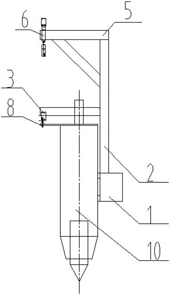
[0024] figure 1 is a schematic diagram of the overall structure of the fiber bearing bracket according to the present invention, and 2 is figure 1 End view of the fiber-carrying bracket shown in . Such as figure 1 and figure 2 As shown in , according to the present invention, the optical fiber bearing support for laser processing equipment is a frame structure, and consists of mutually parallel beams 1 and optical fiber bearing supports 5, as well as left column 2 and right column 2' across the two Composed together. The beam 1 has a linear guide rail 9, on which the laser head 10 is arranged...


PUM


Abstract

The invention discloses an optical fiber bearing bracket of laser processing equipment, which adopts a framework structure, wherein the framework structure comprises a cross beam, an optical fiber bearing support, a left column and a right column; the cross beam and the optical fiber bearing support are parallel to each other; the left column and the right column span the cross beam and the optical fiber bearing support; the cross beam serves as a rail on which a laser head moves left and right; a hook component is arranged on the optical fiber bearing support, comprises a plurality of hooks which are distributed at intervals integrally, and can move left and right along the optical fiber bearing support; an optical fiber is led out of an optical fiber laser, and wound around the hooks in sequence in a ring-shaped manner; the tail end of the optical fiber is connected to the laser head; three pulleys are arranged on the optical fiber bearing support, the left column and the right column respectively; and two cables pass through the three pulleys clockwise and counterclockwise respectively, and are connected to the left and the right sides of the laser head and those of the hook component respectively, so that the laser head and the optical fiber move synchronously. According to the invention, the optical fiber can be fed stably and reliably during a laser processing process, and the fracture of the optical fiber can be avoided effectively.

Description

technical field [0001] The invention belongs to the technical field of laser processing, and more specifically relates to an optical fiber bearing bracket of laser processing equipment. Background technique [0002] Laser processing technology refers to the use of high-energy laser beams to cut, weld, mark, engrave, surface treatment, and micro-machining processes on the surface of materials or parts. Automotive, metallurgy, aerospace, machinery, microelectronics, instrumentation and other fine processing fields. The laser processing system usually consists of five parts, namely the laser, the light guide system, the laser processing equipment body, the laser processing head device and the processing table. The thermal effect of the workpiece thus realizes the processing process on the workpiece. Lasers currently used for processing mainly include CO 2 lasers, Nd:YAG solid-state lasers and fiber lasers. [0003] As the third-generation laser, fiber laser uses optical fib...

Claims


Application Information

Patent Timeline
Patent Type & Authority Applications(China)
IPC IPC(8): B23K26/00B23K26/08B23K26/70
Inventor 黄禹段正澄李斌柳懿麟张尚蒋志伟王启行
Owner HUAZHONG UNIV OF SCI & TECH
Why Eureka
Try Eureka