Three-axis mobile positioning high-loading integrated machine

A high-load, axis-moving technology, applied in the direction of drive devices, metal processing machinery parts, metal processing equipment, etc., can solve the problems of small load, low precision of all-in-one machines, and inability to move multiple axes, so as to achieve sufficient operating power and improve accuracy Effect

Pending Publication Date: 2019-03-01
弗彧锦(上海)智能设备有限公司
View PDF6 Cites 0 Cited by
  • Summary
  • Abstract
  • Description
  • Claims
  • Application Information

AI Technical Summary

Problems solved by technology

[0004] The purpose of the present invention is to provide a three-axis mobile positioning high-load all-in-one machine, which is used to solve the problems of low precision, small load and inability to move in multiple axes in the existing all-in-one machine

Method used


Image

  • Three-axis mobile positioning high-loading integrated machine
  • Three-axis mobile positioning high-loading integrated machine
  • Three-axis mobile positioning high-loading integrated machine

Examples


Embodiment 1

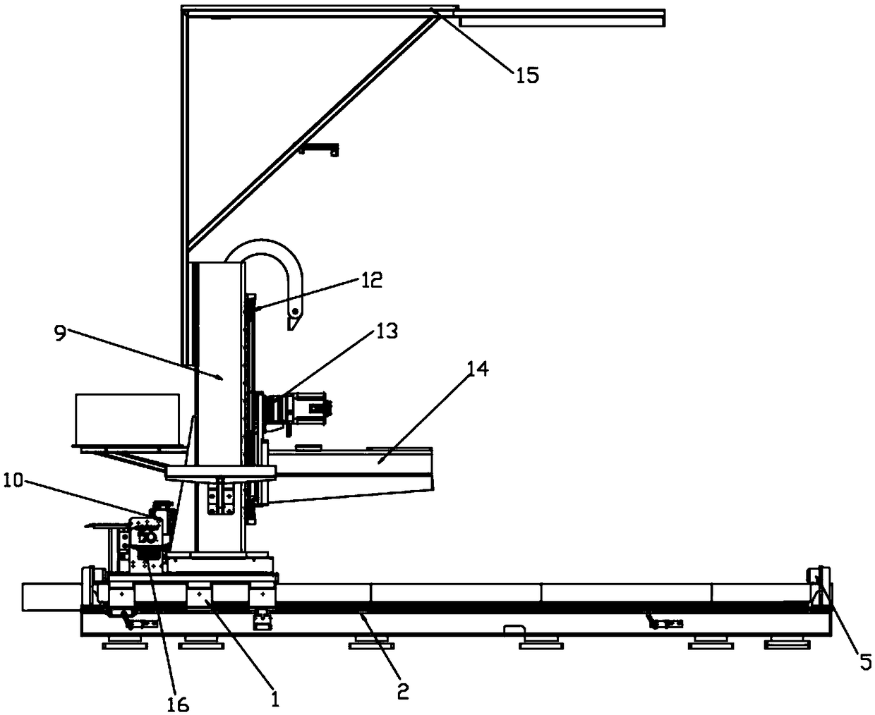
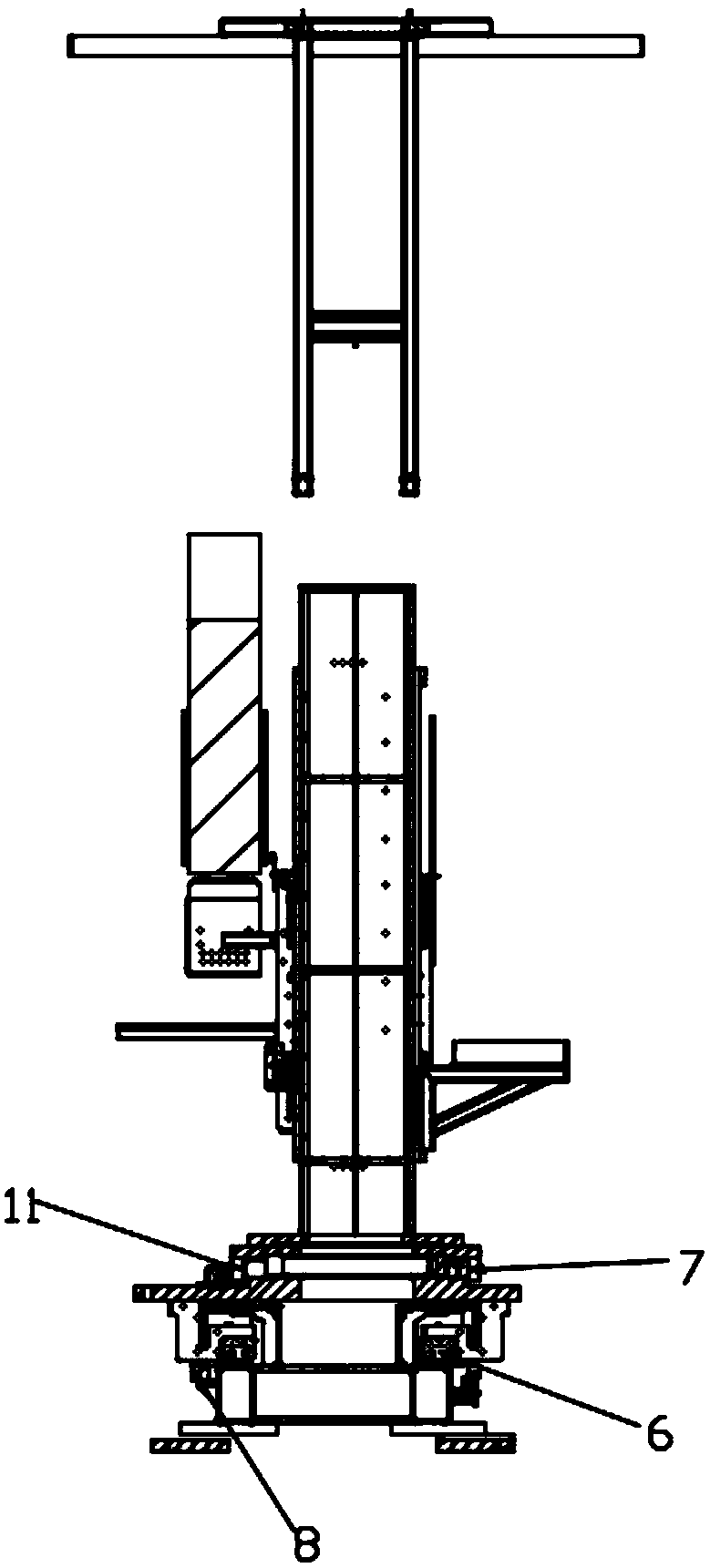
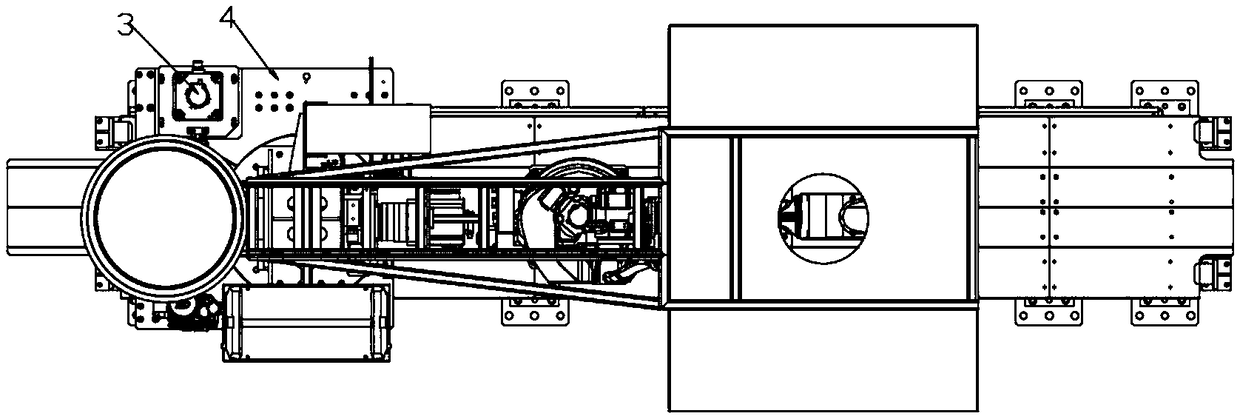
[0026] see Figure 1~5 , in an embodiment of the present invention, a three-axis mobile positioning high-load all-in-one machine, including a slide plate 1, an X-direction travel shaft 2, a first reducer 3, an X-direction mobile slide plate 4, a limit switch 5, a linear guide rail 6, an X To the rack and pinion 8, the third reducer 10, the second reducer 13 and the automatic pressurized grease lubrication system, the linear guide rail 6 is located on the X-direction travel axis 2, and the X-direction moving slide plate 4 passes through the bottom slide plate 1 Slidingly connected with the linear slide rail 6, the X-direction mobile slide plate 4 is fixedly connected with the slide plate 1, the bottom of the slide plate 1 is provided with a first gear 17, and the first reducer 3 is connected to the first gear rack 8 through the X-direction The meshing of the gear 17 drives the X-direction mobile slide plate 4 to move automatically. The X-direction gear rack 8 is located on the ...

Embodiment 2

[0029] The difference between this embodiment of the present invention and Embodiment 1 is that a connecting smoke exhaust bracket 15 and an automatic pressurized grease lubrication system 16 are provided above the Z-direction rotating shaft 9, and the connecting smoke exhaust bracket 15 is located at the top of the device. The automatic pressurized grease lubrication system 16 is located on one side of the third reducer 10 .

[0030] The working principle of the present invention is: when the X-direction walking shaft 2 needs to walk, the first reducer 3 drives the X-direction rack and pinion 8 to move, and can move to the specified position. Or when the tail end hits the limit switch 5, the X-direction mobile slide plate 4 stops; when the Z-direction rotating shaft 9 needs to rotate, the third reducer 10 drives the high-load bearing 7 and the Z-direction rack and pinion 11 to rotate, The second reducer 13 can drive Z to move up and down the moving shaft 14 and stop at any po...


PUM


Abstract

The invention discloses a three-axis mobile positioning high-loading integrated machine and relates to the mechanical field. The machine mainly aims to solve the problem that an existing integrated machine has low precision, small loading and no multi-axis movement; the three-axis mobile positioning high-loading integrated machine comprises a sliding plate, an X-direction walking shaft, a first reducer, an X-direction moving slide plate, a linear guide rail and an X-direction gear rack, the X-direction moving slide plate is driven by the first reducer to automatically move through meshing between the X-direction gear rack and a first gear, the upper portion of the X-direction moving slide plate is provided with a high-loading bearing, the upper portion of the X-direction moving slide plateis also provided with a Z-direction rotating shaft and a third reducer, the bottom of the Z-direction rotating shaft is provided with a second gear, and the Z-direction rotating shaft can make rotation and accurate positioning under driving of the third reducer through the meshing between the second gear and the Z-direction gear rack. The three-axis mobile positioning high-loading integrated machine has the advantages that the accuracy of the integrated machine is greatly improved and multi axial movement is realized.

Description

technical field [0001] The invention relates to the field of machinery, in particular to a three-axis mobile positioning high-load all-in-one machine. Background technique [0002] An all-in-one machine refers to a machine that assembles multiple components together to achieve multiple functions. The all-in-one machine has strong functionality and can meet various needs. The all-in-one machine occupies a large proportion in industrial production and is indispensable for industrial production. Part of it improves the efficiency of production, reduces the workload of workers, and brings greater production value. [0003] The existing all-in-one machine has low precision, small load, and short stroke. At the same time, the current all-in-one machine has only a single stroke and can only move in a single direction, which cannot satisfy multi-axis motion. At the same time, the lubrication effect is poor, so manual lubrication is often required , Caused very big inconvenience, so...

Claims


Application Information

Patent Timeline
Patent Type & Authority Applications(China)
IPC IPC(8): B23Q5/04
CPCB23Q5/04
Inventor 蓝海盛
Owner 弗彧锦(上海)智能设备有限公司
Why Eureka
Try Eureka