Current assisted method for quickly preparing powder

A powder and fast technology, applied in the field of current-assisted rapid powder preparation, to achieve fast powder reaction, simple design, and shortened time

Active Publication Date: 2013-12-25
NINGBO INST OF MATERIALS TECH & ENG CHINESE ACADEMY OF SCI
View PDF5 Cites 0 Cited by
  • Summary
  • Abstract
  • Description
  • Claims
  • Application Information

AI Technical Summary

Problems solved by technology

However, when the powder is sintered using the above-mentioned current-assisted sintering device, due to the structural characteristics of the current reaction chamber, the powder can only be sintered in the end although it has undergone phase change and solid-state reaction during the sintering process. Fully dense or partially dense blocks, rather than maintaining the original powder form

Method used


Image

  • Current assisted method for quickly preparing powder
  • Current assisted method for quickly preparing powder
  • Current assisted method for quickly preparing powder

Examples


Embodiment 1

[0035] In this example, the method of current-assisted rapid preparation of powder is as follows:

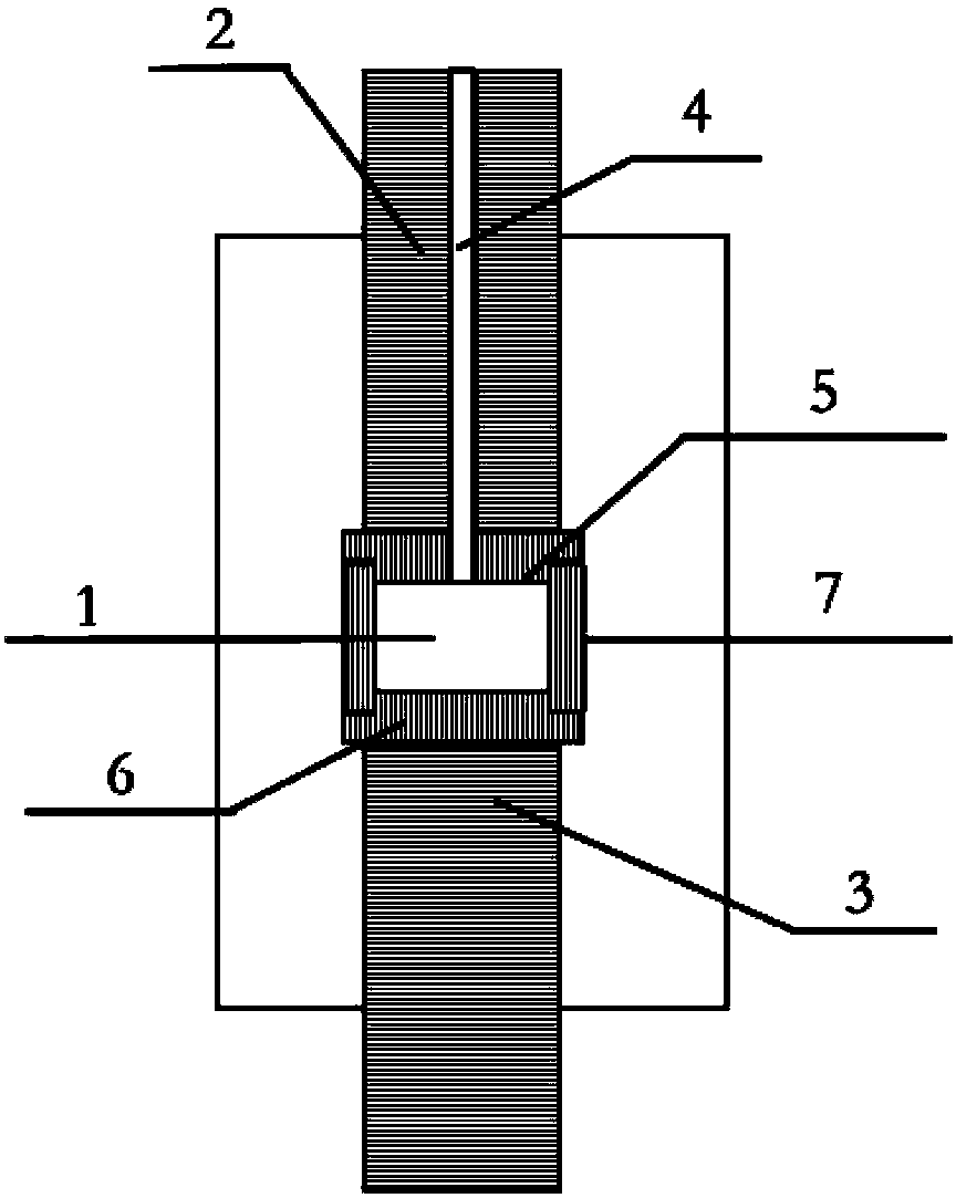
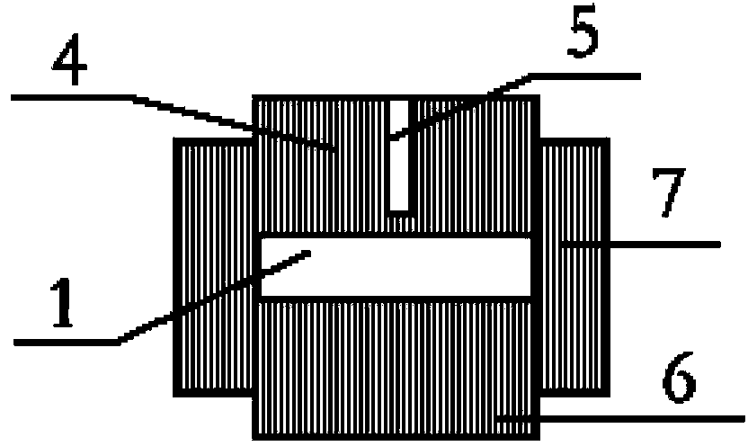
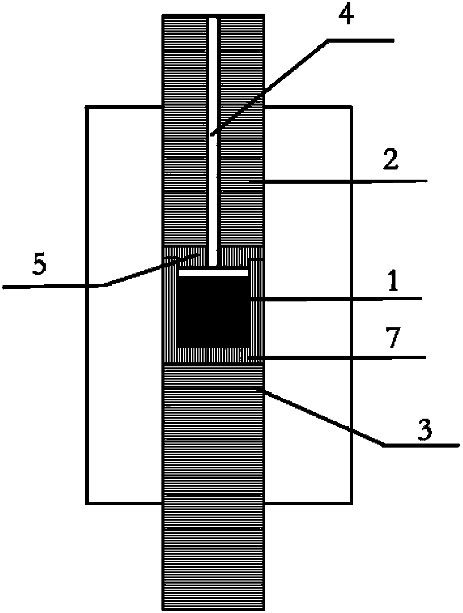
[0036] A current-assisted rapid powder preparation device is used, and the structural schematic diagram of the device is shown in image 3 As shown, it includes a reaction chamber 1 for placing powder, upper and lower electrode pressure heads 2 and 3 connected to the reaction chamber 1 . The reaction chamber 1 is a closed space surrounded by the chamber side wall 7, the upper end cover 5 and the lower end cover 6, the upper end cover 5 is connected with the upper electrode pressure head 2, the lower end cover 6 is connected with the lower electrode pressure head 3, and The volume of this enclosed space is fixed. The upper end cover 5 is provided with a temperature measuring hole 4 for placing a temperature measuring component to monitor the temperature in the reaction chamber 1, and the temperature measuring component is an upper infrared thermometer. Such as Figure 4 As sho...

Embodiment 2

[0043] In this example, the method of current-assisted rapid preparation of powder is as follows:

[0044] A current-assisted rapid powder preparation device is used, and the structural diagram of the device is similar to image 3 As shown, it includes a reaction chamber 1 for placing powder, upper and lower electrode pressure heads 2 and 3 connected to the reaction chamber 1 . The reaction chamber 1 is a closed space surrounded by the side wall 7 of the chamber, the upper end cover 5 and the lower end cover 6, the upper end cover 5 is connected with the upper electrode pressure head 2, the lower end cover 6 is connected with the lower electrode pressure head 3, and The volume of this enclosed space is fixed. The upper end cover 5 is provided with a temperature measuring hole 4 for placing a temperature measuring component to monitor the temperature in the reaction chamber 1, and the temperature measuring component is an upper infrared thermometer. Such as Figure 5 As show...


PUM


Abstract

The invention provides a current assisted method for quickly preparing powder. A current assisted device for quickly preparing powder is adopted. A reaction cavity of the device is a sealed space enclosed by a side wall and the upper and lower end covers of the cavity. The upper and lower end covers are respectively connected with pressure heads of the upper and lower electrodes. In a work state, pressure generated by the pressure heads of the upper and lower electrodes is borne by the side wall and the upper and lower end covers of the cavity. The volume of the sealed space is invariable. The method comprises the steps of: first, placing the powder in the reaction cavity; then, connecting a direct current or a high frequency pulse current between the pressure heads of the upper and lower electrodes, wherein the current generates heat through the reaction cavity and the powder is heated quickly; measuring temperature of the reaction cavity through a temperature measuring part; shutting down the current when the temperature rises the predetermined temperature and is maintained for a period of time; and taking out the powder after the cavity is cooled. According to the method provided by the invention, the current assisted sintering principle is combined into a powder preparation process, and powder such as metal, ceramic and the like can be rapidly prepared conveniently and quickly, so that the method provided by the invention has good application prospect.

Description

technical field [0001] The invention relates to the technical field of powder preparation of metals, ceramics, etc., in particular to a method for rapid preparation of powders assisted by electric current. Background technique [0002] Current-assisted sintering technology (EAST) is a sintering process that uses direct current or high-frequency pulse current to achieve rapid temperature rise, while applying pressure at both ends of the electrode to achieve high thermal efficiency. The sintering method is also called electric field assisted sintering (EFS), electric field activated sintering (EAS), pulse current activated pressure sintering (PECPS) and spark plasma sintering (SPS). [0003] At present, devices that can realize current-assisted sintering technology such as figure 1 As shown, it mainly includes the reaction chamber 1 for placing the material to be sintered, the upper and lower electrode pressure heads 2 and 3 arranged at both ends of the reaction chamber 1, an...

Claims


Application Information

Patent Timeline
Patent Type & Authority Patents(China)
IPC IPC(8): B22F3/105
Inventor 黄庆胡春峰申璐周小兵汪乾
Owner NINGBO INST OF MATERIALS TECH & ENG CHINESE ACADEMY OF SCI
Why Eureka
Try Eureka