Driving device of gear-synchronous cog belt numerical control plate shearing machine

A synchronous toothed belt and driving device technology, applied in the direction of shearing devices, shearing machine equipment, metal processing equipment, etc., can solve the problems of low transmission efficiency, oil leakage environment, difficult maintenance, etc., and achieve the improvement of shearing width and Accuracy, improved work ability, and improved work efficiency

Inactive Publication Date: 2012-10-24
SUZHOU UNIV
View PDF7 Cites 3 Cited by
  • Summary
  • Abstract
  • Description
  • Claims
  • Application Information

AI Technical Summary

Problems solved by technology

Among them, the main technical problems of the hydraulic shearing machine are: (1) oil leakage causes environmental pollution; (2) low transmission efficiency, resulting in a large waste of energy; (3) hydraulic components such as pumps and valves are expensive, Difficult to maintain; (4) Large-scale hydraulic shears require a large flow rate of the hydraulic pump and a large volume of the fuel tank, resulting in a large system volume
The main technical problems of the pneumatic shearing machine are: (1) the system pressure is low, so it can only be used in occasions with small shearing force; (2) the gas is compressible, and the synchronous circuit cannot be used like the hydraulic shearing machine. Therefore, it cannot be used in occasions where the cutting width is large
[0005] The automation control level of the above-mentioned technical scheme is low. At the same time, due to the structural setting of the shearing machine drive device, linear guide rails are set on both sides to guide the linear motion, and the increase in the width of the tool holder is limited. When trying to make a large shearing machine, The mechanical structure of the device is relatively complex, which increases the difficulty of manufacturing, increases the manufacturing cost, and cannot guarantee the shearing accuracy

Method used


Image

  • Driving device of gear-synchronous cog belt numerical control plate shearing machine

Examples


Embodiment 1

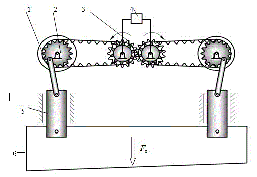
[0021] Embodiment one: see figure 1 As shown, a gear-synchronous toothed belt CNC shearing machine driving device includes a connecting rod 1, a synchronous toothed wheel 2, a servo motor 3, a numerical control system 4, a slider 5 and a tool holder 6.

[0022] The tooth profile of the synchronous toothed belt and the teeth of the synchronous toothed wheel 2 mesh successively to transmit motion and power. The gear engagement ensures that the rotating speeds of the left and right synchronous toothed wheels 2 are the same, and the actions of the left and right sliding blocks connected thereto also guarantee synchronization.

[0023] The synchronous toothed wheel 2 drives the slider 5 through the connecting rod 1 to drive the knife rest 6 to reciprocate up and down, so as to realize the function of cutting the plate.

[0024] The working principle of the gear-synchronous toothed belt CNC shearing machine driving device is as follows:

[0025] When the numerical control system 4...


PUM


Abstract

The invention discloses a driving device of a gear-synchronous cog belt numerical control plate shearing machine. The driving device of the gear-synchronous cog belt numerical control plate shearing machine comprises a power device, a transmission device, a control device and a movable knife rest and is characterized in that the power device is a servo motor, the transmission device comprises a gear, a synchronous toothed wheel, a synchronous cog belt, a connecting rod and a sliding block, wherein the gear, the synchronous cog belt, the connecting rod and the sliding block are arranged on an output shaft of the servo motor. The gear and the synchronous toothed wheel are in transmission through the synchronous cog belt, one end of the connecting rod is in transmission connection with the synchronous toothed wheel, the other end of the connecting rod is in transmission connection with one end of the sliding block, the other end of the sliding block is fixedly connected with the movable knife rest, the sliding block is limited by a linear motion limit mechanism which is consistent with the motion direction of the movable knife rest, and the control device is a numerical control system. The driving device of the gear-synchronous cog belt numerical control plate shearing machine achieves shearing of wide plates, improves working capacity, simultaneously is ingenious in design, has belt transmission, gear transmission and chain transmission, can effectively guarantee shearing accuracy, improves working efficiency, is simple in structure, and reduces manufacturing cost.

Description

technical field [0001] The invention relates to a numerically controlled plate shearing machine, in particular to a plate shearing machine whose driving device is a gear-synchronous toothed belt. Background technique [0002] Shearing machine is a shearing equipment for cutting and processing plates according to size requirements. It is the most widely used material cutting equipment in various industrial sectors. It is mainly used to cut straight edges of various sizes of metal plates and has a wide range of applications in the manufacturing field. CNC shearing machine refers to a device that uses digital instructions composed of numbers, words and symbols to realize the movement control of one shearing machine or multiple shearing machines. [0003] With the extensive use of metal sheets, shearing machines have been widely used in metallurgy, petrochemical, machinery and other industrial sectors. The driving device is an important device on the shearing machine, and it is...

Claims


Application Information

Patent Timeline
Patent Type & Authority Applications(China)
IPC IPC(8): B23D15/12B23D15/06
Inventor 王传洋钟康民钟以波
Owner SUZHOU UNIV
Why Eureka
Try Eureka