Eureka AIR delivers breakthrough ideas for toughest innovation challenges, trusted by R&D personnel around the world.

High-current battery system and method for controlling a high-current battery system

A battery system, high current technology, applied in battery/fuel cell control devices, battery circuit devices, different battery charging and other directions, can solve the problems of high current switching expensive and increasing costs

Inactive Publication Date: 2012-10-17
INNOLITH ASSESTS AG
View PDF17 Cites 15 Cited by
  • Summary
  • Abstract
  • Description
  • Claims
  • Application Information

AI Technical Summary

Problems solved by technology

However, the disadvantage of high current switching is that it is very expensive
Also, separate switches must be used for each battery or cell
This increases costs accordingly, especially when a large number of battery cells are used in electric vehicles

Method used


Image

  • High-current battery system and method for controlling a high-current battery system
  • High-current battery system and method for controlling a high-current battery system
  • High-current battery system and method for controlling a high-current battery system

Examples


Embodiment Construction

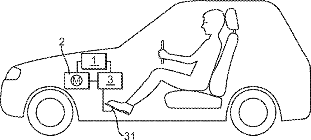
[0047] figure 1 An electric vehicle is shown having a high current battery system 1 according to the invention, an electric motor 2 and an electric motor control unit 3 controlling the electric motor 2 . Transmitter 31 for electric motor control unit 3 is designed as an electronic accelerator pedal. However, the transmitter 31 may also be a manual controller or the like. When the electric vehicle is running, more or less energy is drained from the high current battery system 1 and delivered to the electric motor 2 depending on the position of the electric "gas pedal" 31 . The current flow is correspondingly sized. When it is recognized that the bypass battery module 6 has a fault state, the load current flowing between the high-current battery system 1 and the electric motor 2 is preferably controlled via the electric motor control unit 3 so that the operating current line of the high-current battery system 1 The current flowing between the plurality of battery modules 4 in...


PUM


Abstract

The present invention relates to a high-current battery system (1) in which a high operating current flows, in particular for vehicle drives. The high-current battery system (1) has a battery system monitoring electronics unit (12) and a plurality of battery modules (4), each module including at least one rechargeable battery cell (10) and being electrically connected in series by means of an operating current line (5) such that an operating current flows through the operating current line (5) during operation. At least one of the battery modules (4) is designed as a bypass battery module (6) which comprises a bypass switch (7) and a bypass line (8), which are designed and disposed such that the battery module (6) is electrically bridged by the bypass line (8) after the bypass switch (7) is switched from a normal operating position into a bypass position, so that the operating current flows through the bypass line (8). For each bypass battery module (6), the battery system monitoring electronics unit (12) incorporates a module monitoring unit (11) which monitors the associated battery module (6) and detects a fault state of the module (6). Upon detection of a fault state of a battery module (6) by one of the module monitoring units (11), the battery system monitoring electronics unit (12) measures the current flow in the operating current line (5) and switches the bypass switch (7) of the battery module (6) in question from the normal operating position into the bypass position at a time at which the current flow in the operating current line (5) is less than a predetermined limit value.

Description

technical field [0001] The invention relates to a high-current battery system in which high operating currents flow and which is particularly suitable for use in vehicle transmissions. The high-current battery system includes a plurality of battery modules, each battery module includes at least one rechargeable battery cell (battery cell), and the plurality of battery modules are electrically connected in series by means of an operating current line so that during operation the operating current Flow through the running current line. Background technique [0002] High current battery systems are used in many mobile devices that require large capacity and are capable of flowing high currents in the range of tens or hundreds of amperes. Examples of the use of high-current battery systems are mobile tools or also vehicles, in particular electric vehicles in which a maximum current in the range from 100 A to approximately 400 A usually flows. But high current battery systems a...

Claims


Application Information

Patent Timeline
Patent Type & Authority Applications(China)
IPC IPC(8): H01M10/42H01M10/48H02J7/00H01M10/052H01M10/0563H02J7/02
CPCH01M10/482Y02E60/12Y02T10/7055H02J7/0021H01M10/0563H01M2300/002H01M10/052Y02T10/7011Y02T10/7005B60L11/1851H01M2200/00H02J7/0026Y02T10/705B60L11/00H01M10/4207B60L58/10H02J2310/48Y02E60/10Y02T10/70H02J7/0013H02J7/0029H02J7/00309H01M2220/20H02J7/0047Y02P70/50
Inventor G.哈姆比策尔J.海特鲍姆M.博尔克C.里普
Owner INNOLITH ASSESTS AG
Why Eureka
Eureka Blog
Learn More