Fan-type motor centrifugal switch

A centrifugal switch and fan technology, applied in electrical components, electromechanical devices, electric components, etc., can solve the problems of increasing the length of the rotating shaft, weakening the elasticity of the moving contact reed, destroying the ecological balance, etc., and achieving the effect of enhancing reliability.

Inactive Publication Date: 2012-10-17
李荣华
View PDF3 Cites 2 Cited by
  • Summary
  • Abstract
  • Description
  • Claims
  • Application Information

AI Technical Summary

Problems solved by technology

[0002] We know that when the motor is started, the starting circuit provides a large starting current. During normal operation, the starting circuit is disconnected, and the working circuit provides a small current. Therefore, the existing motor must be equipped with a centrifugal switch to control the working state of the motor starting circuit. , The contacts of the existing centrifugal switches at home and abroad are installed on the inner end cover of the motor, and the centrifuge of the centrifugal switch is installed on the inner shaft of the motor. The contact sticks and burns out the motor; when the motor is running, the internal temperature rises, and there is a certain magnetic flux leakage in the stator and rotor, so the centrifugal switch has a single material selection standard and cannot be replaced, otherwise it will not meet the technical requirements for starting, resulting in motor failure. The fixing plate of the fixed contact is made of glass fiber cloth, and the insulating sleeve of the centrifuge is made of powder concrete. The two materials cannot be recycled and recycled. The processing waste and discarded switches are buried in the ground as garbage, which seriously pollutes the environment and bury the earth permanently. Invisible nuclei, destroying the ecological balance
In the process of producing finished products of the two materials, glass dust can seriously harm people's physical and mental health, and the sick cannot be cured.
The moving contact spring is made of zinc-coated copper or stainless steel with strong elasticity. The balance plate of the centrifugal switch is made of brass or stainless steel to prevent the switch from being out of control caused by magnetic flux leakage. The moving contact spring and the fixed contact are large , the material utilization rate only accounts for 50%, which leads to high cost; the external shaft of the motor is equipped with a cooling fan, and the centrifugal switch is installed in the motor. The fan and centrifugal switch are set separately, which increases the length of the shaft and limits the The effective utilization rate of the motor body is reduced, and the power of the motor cannot be increased. The centrifugal switch is installed inside the motor. There are disadvantages such as the maintenance of the motor and the inconvenience of replacing the switch.

Method used


Image

  • Fan-type motor centrifugal switch
  • Fan-type motor centrifugal switch
  • Fan-type motor centrifugal switch

Examples


Embodiment Construction

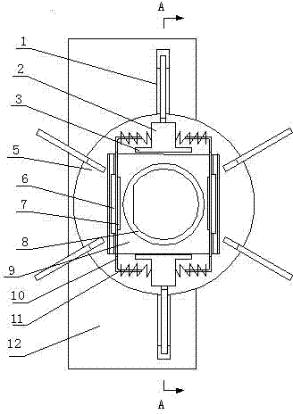
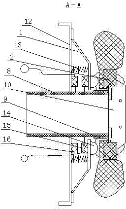
[0020] The centrifugal switch of the fan type motor as shown in the figure is provided with a rotating shaft, and the fan impeller 5 is sleeved axially slidably on the rotating shaft. figure 1 , figure 2 It can be seen that the rotating shaft is an axle sleeve 8, which is more convenient to connect the present invention with the motor shaft during use. The present invention is characterized in that the upper and lower sides of the front side of the fan impeller 5 are provided with two-way spring seats 2, the two-way spring seats 2 are symmetrical and parallel to each other, and the rotating shaft on the front side of the fan impeller 5 is provided with a centrifugal counterweight clamping plate 9. The upper and lower sides of the plate 9 are stuck between the two spring seats 2, so that the fan impeller 5 can only move axially relative to the centrifugal counterweight clamp plate 9, and cannot rotate relatively. It can be seen from the figure that the two spring seats 2 are o...


PUM


Abstract

The invention discloses a fan-type motor centrifugal switch which relates to the field of an electric appliance switch. The fan-type motor centrifugal switch is provided with a rotating shaft, wherein the rotating shaft is provided with a fan impeller; the upper side and the lower side of the front side surface of the fan impeller are provided with bidirectional spring seats; the spindle on the front side of the fan impeller is provided with a centrifugal counter weight snap-gauge; the centrifugal counter weight snap-gauge is clamped between the two spring seats; the left end part and the right end part of the centrifugal counter weight snap-gauge are hinged with centrifugal plates; the upper end part and the lower end part of each centrifugal plate are provided with elastic sheathing arms; the centrifugal plate and the centrifugal counter weight snap-gauge are hinged with the each other; each elastic sheathing arm is sheathed with a closed spring; the other end of the closed spring is abutted against the spring seats; the rear side of the fan impeller is provided with an insulation plate; and a return spring and a travel switch are arranged between the insulation plate and the travel switch. According to the fan-type motor centrifugal switch disclosed by the invention, each component can be made of ABS (acrylonitrile butadiene styrene) plastic products, and the production and the use of materials are both environment-friendly and free from pollution. The fan-type motor centrifugal switch has the advantages of small volume, light weight, cost saving, low structural requirement on a motor shaft, manpower saving, low cost, convenience in installing and maintaining and high effective use ratio of the inside of a motor body, and the improvement of power of the motor.

Description

technical field [0001] The invention relates to the field of electrical switches, and specifically relates to a fan-type motor centrifugal switch with safety and environmental protection, low cost, and convenient installation and maintenance. Background technique [0002] We know that when the motor is started, the starting circuit provides a large starting current. During normal operation, the starting circuit is disconnected, and the working circuit provides a small current. Therefore, the existing motor must be equipped with a centrifugal switch to control the working state of the motor starting circuit. , The contacts of the existing centrifugal switches at home and abroad are installed on the inner end cover of the motor, and the centrifuge of the centrifugal switch is installed on the inner shaft of the motor. The contact sticks and burns out the motor; when the motor is running, the internal temperature rises, and there is a certain magnetic flux leakage in the stator...

Claims


Application Information

Patent Timeline
Patent Type & Authority Applications(China)
IPC IPC(8): H02K11/00H02K11/20
Inventor 李荣华
Owner 李荣华
Why Eureka
Try Eureka