Connecting and sealing structure of oral implant-base

An oral implant and sealing structure technology, applied in dental implants, medical science, dentistry, etc., can solve problems such as soft tissue and bone tissue cannot exist stably for a long time, blood vessels cannot grow in, soft tissue inflammation, etc., to avoid cortical bone atrophy and Microbial growth, reducing bone stress concentration and shielding, alleviating the effect of neck stress concentration

Active Publication Date: 2012-10-17
SICHUAN UNIV
View PDF5 Cites 14 Cited by
  • Summary
  • Abstract
  • Description
  • Claims
  • Application Information

AI Technical Summary

Problems solved by technology

At present, the main problems in the field of oral implant include: 1. Bone resorption at the implant-abutment interface: According to previous research, the implant-abutment interface will occur vertically 1-2mm and horizontally about 1.5mm one year after implantation 2. Implant-abutment interface micro-gap: Although modern processing technology is increasingly advanced, there is inevitably a micro-gap at the interface between the implant and the abutment. On the one hand, it provides a channel for microbial leakage inside and outside the implant, and on the other hand, it causes micro-movement of the implant components; 3. Mechanical grinding of the implant-abutment interface: the micro-motion between the implant components causes the implant surface and the abutment to fret. External mechanical grinding, when the abutment is stressed, metal fines may be "pumped out" of the implant-abutment interface and enter the surrounding soft tissue, causing discoloration of the soft tissue and other problems; 4. Soft and hard tissue inflammation around the micro-gap: implants Microorgani

Method used


Image

  • Connecting and sealing structure of oral implant-base
  • Connecting and sealing structure of oral implant-base
  • Connecting and sealing structure of oral implant-base

Examples


Embodiment Construction

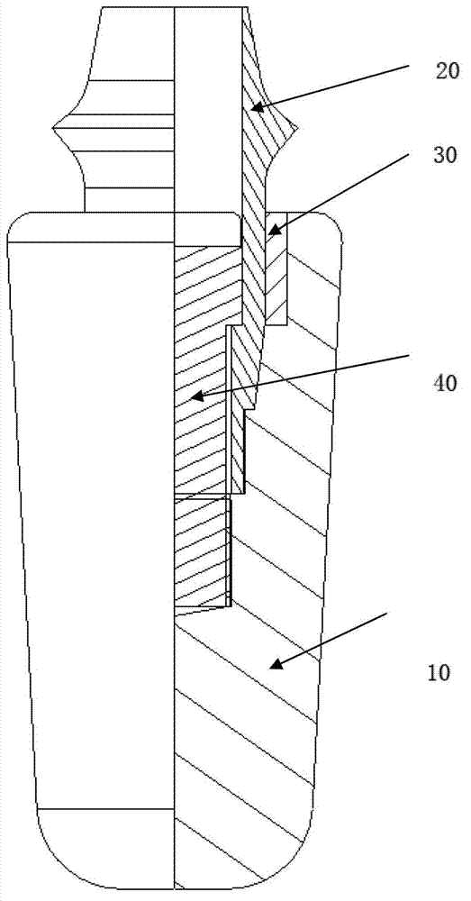
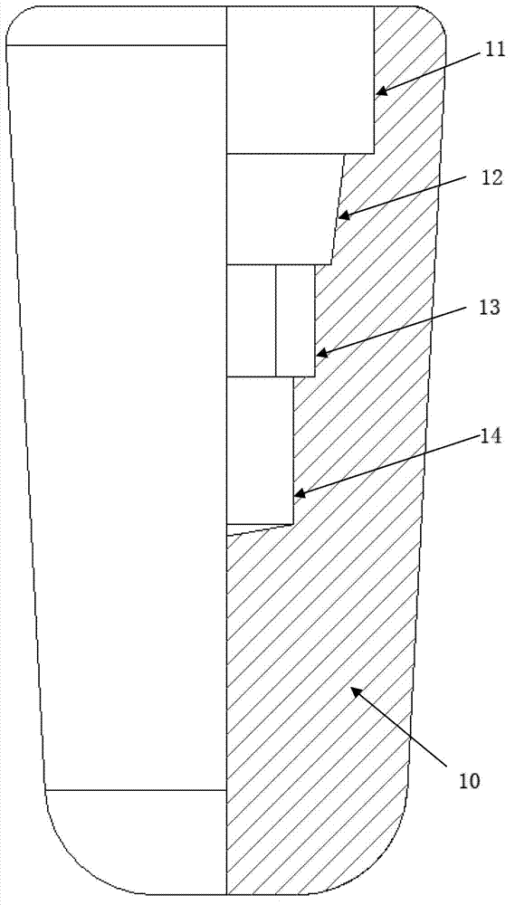
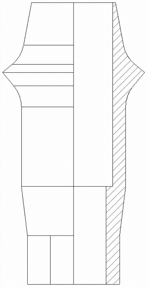
[0019] The present invention is a novel oral implant-abutment connection and sealing structure. The neck of the implant 10 is provided with an upper cylindrical hole 11, a middle conical hole 12, a positioning hole 13, and a lower threaded hole 14; the upper cylindrical hole 11 A sealing ring 30 with a thickness of 0.1-0.5mm is provided between the abutment 20; the height of the sealing ring 30 is 0.5-5mm. The abutment 20 and the implant are connected by a connecting screw 40 . The sealing ring is made of biomedical polymer material. The elastic modulus of the biomedical polymer material is 1-1000Mpa. The biomedical polymer material is polytetrafluoroethylene, silicon rubber or natural rubber. The cone angle of the conical hole 12 in the middle section is 2°51′26″˜3°00′53″.

[0020] The present invention is provided with sealing ring between implant body and abutment, and this sealing ring has brought following effect:

[0021] (1) The medical polymer material used in the ...


PUM

PropertyMeasurementUnit
Thicknessaaaaaaaaaa
Heightaaaaaaaaaa
Elastic modulusaaaaaaaaaa

Abstract

The invention provides a novel connecting structure of an oral implant-base. A neck part of an implant is provided with an upper columnar hole, a middle taper hole, a positioning hole, and a lower thread hole from top to bottom; a sealing ring with the thickness of 0.1-0.5 mm is arranged between the upper columnar hole and the base. The sealing ring is made of medical high polymer material (polytetrafluoroethylene, silicon rubber, natural rubber, and the like); the neck part of the implant is connected with the base to remove a microgap between the base and the implant and stop the stress transmitting to the neck part of the implant directly; therefore, the structure has the function of adjustable stress transmission and distribution, the intensity of directly transmitting the implant stress to a cortical bone can be reduced, the absorption of the cortical bone can be removed or decreased; the structure is beneficial to reconstructing the physiology of bone organizations around the implant; meanwhile, with the adoption of the structure, the negative effects of the microgap between the implant and the base, and the metal grinding are avoided; the problems of atrophic cortical bone and bred microorganisms are effectively avoided.

Description

technical field [0001] The invention relates to an oral implant-abutment connection sealing structure, which belongs to the field of medical instruments. Background technique [0002] The oral implant device is the main part of the current oral implant denture. At present, the main problems in the field of oral implant include: 1. Bone resorption at the implant-abutment interface: According to previous research, the implant-abutment interface will occur vertically 1-2mm and horizontally about 1.5mm one year after implantation 2. Implant-abutment interface micro-gap: Although modern processing technology is increasingly advanced, there is inevitably a micro-gap at the interface between the implant and the abutment. On the one hand, it provides a channel for microbial leakage inside and outside the implant, and on the other hand, it causes micro-movement of the implant components; 3. Mechanical grinding of the implant-abutment interface: the micro-motion between the implant c...

Claims


Application Information

Patent Timeline
IPC IPC(8): A61C8/00
Inventor 田卫东聂晶罗教明刘磊莫安春廖运茂孟玉坤何勤礼
Owner SICHUAN UNIV
Why Eureka
Try Eureka