Eureka AIR delivers breakthrough ideas for toughest innovation challenges, trusted by R&D personnel around the world.

Solar battery diffusion method

A solar cell and diffusion method technology, applied in the field of crystalline silicon solar cell manufacturing, can solve problems such as reduced filling, increased series resistance, and low-efficiency sheets in the production line, so as to reduce surface recombination and defect concentration, increase conversion efficiency, and improve The effect of conversion efficiency

Active Publication Date: 2012-10-10
JIANGSU HOYI TECH
View PDF3 Cites 14 Cited by
  • Summary
  • Abstract
  • Description
  • Claims
  • Application Information

AI Technical Summary

Problems solved by technology

[0004] Diffusion technology generally pursues shallow junctions at present, and the junction depth is about 200nm. The main reason is that shallow junctions can better absorb sunlight. Shallow junctions correspond to the short-wavelength spectrum of sunlight. More, you can get a better blue wave response, thereby increasing the short-circuit current, and the shortcoming brought by the shallow junction is that the shallow junction causes the solar cell absorption spectrum to blue shift, and the PE section process needs to be adjusted to match the shallow junction of the spectrum Absorption, component packaging causes excessive power loss due to spectral mismatch; at the same time, shallow junctions cause increased series resistance and reduced filling, which affects battery efficiency. Shallow junctions are easy to burn through, resulting in an increase in low-efficiency chips in the production line
The emergence of Selective Emitter technology (Selective Emitter) has solved the problem of large series resistance, but the use cost of Selective Emitter technology is higher than that of conventional technology, and it needs to add one or two processes, so that the industry has not carried out large-scale mass production

Method used


Image

  • Solar battery diffusion method

Examples


Embodiment 1

[0046] The raw material is P-type monocrystalline silicon wafer, the thickness is 200±20um, and the resistivity is 0.5-6W.cm. Place the slices in a diffusion furnace.

[0047] Step 1, the first oxidation

[0048] The temperature of the diffusion furnace is raised to 820°C, the flow rate of oxygen is 10slm, and the time of oxygen is 15min to form a 20nm oxide layer;

[0049] Step 2. Diffusion

[0050] 2.1, the first diffusion

[0051] The diffusion furnace is heated to 840°C, the flow rate of the small nitrogen is 1.2 slm, the flow rate of the large nitrogen is 9 slm, the flow rate of the oxygen is 1.3 slm, and the time for feeding the mixed gas is 6 minutes;

[0052] 2.2, the second diffusion

[0053] The diffusion furnace is heated to 850°C, the flow rate of the small nitrogen is 1.0 slm, the flow rate of the large nitrogen is 9 slm, the flow rate of the oxygen is 1.2 slm, and the time for feeding the mixed gas is 5 minutes;

[0054] 2.3. The third diffusion

[0055] Th...


PUM


Abstract

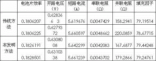
The invention relates to a solar battery diffusion method which is characterized by comprising a step I of first oxidation, a step II of diffusion and a step III of second oxidation. The step II of diffusion comprises primary diffusion, the secondary diffusion and tertiary diffusion. In the solar battery diffusion method provided by the invention, a P-type silicon wafer is used as a diffusion source substrate; through three sub-steps of diffusion in the diffusion stage, the inlet flow of nitrogen and oxygen turns from large to small, and the inletting time turns from long to short; in the step III, the concentration of a phosphorus source is driven into the substrate from high to low, thus the surface concentration is gradually reduced, and the surface recombination and defect concentration is reduced; gradient doping is formed, the P-N junction area is widened, and the open-circuit voltage is increased; and meanwhile, through the relatively deep junction, the series resistance can be reduced, and the conversion efficiency of a solar battery is improved. The solar battery diffusion method does not need an additional process, is relatively low in cost and can be used for improving the conversion efficiency of the crystalline silicon solar battery.

Description

technical field [0001] The invention relates to a solar cell diffusion method, and more particularly to a diffusion method for improving the conversion efficiency of the solar cell. The method can be widely used in the manufacture of crystalline silicon solar cells and belongs to the field of crystalline silicon solar cell manufacturing. Background technique [0002] After more than ten years of industrial development of solar cells, its process has gradually matured and optimized, and diffusion is the core step of the manufacturing process, and the improvement of its process directly affects the improvement of battery efficiency. [0003] At present, tubular diffusion is commonly used in the field of crystalline silicon solar cell manufacturing, which is easy to operate; most of the diffusion methods use one-step diffusion to form a P-N junction, and the concentration gradient is small, making it difficult to realize the N+-N-P structure. [0004] Diffusion technology gener...

Claims


Application Information

Patent Timeline
IPC IPC(8): H01L21/223
Inventor 闫循磊杨贵忠许谦
Owner JIANGSU HOYI TECH
Why Eureka
Eureka Blog
Learn More