
Superconducting magnet joint and manufacturing method thereof

A technology of superconducting magnets and superconducting joints, applied in superconducting magnets/coils, magnetic objects, superconducting devices, etc., can solve problems such as unsuitable for engineering use, harsh environmental requirements, and cumbersome manufacturing processes, and achieve simple structure , the production and maintenance are large, and the production method is simple

Active Publication Date: 2012-10-10
西安聚能医工科技有限公司
View PDF5 Cites 13 Cited by
  • Summary
  • Abstract
  • Description
  • Claims
  • Application Information

AI Technical Summary

Problems solved by technology

In the former category of methods, the patent 201010221920.8 of the Institute of Electrical Engineering, Chinese Academy of Sciences announced a bronze process Nb 3 Sn superconductor multi-core wire joints and their preparation methods have also been published in foreign countries. The production process is cumbersome and is one-time molding. If the joints are not handled properly after heat treatment, there is a huge risk of damage to the magnets.
Among the latter methods, GE Company of the United States once used chemical vapor deposition (CVD) to deposit superconducting layers on the joints. This method is complex in process and harsh in the environment, and is not suitable for engineering use.

Method used


Image

  • Superconducting magnet joint and manufacturing method thereof
  • Superconducting magnet joint and manufacturing method thereof
  • Superconducting magnet joint and manufacturing method thereof

Examples


Embodiment 1

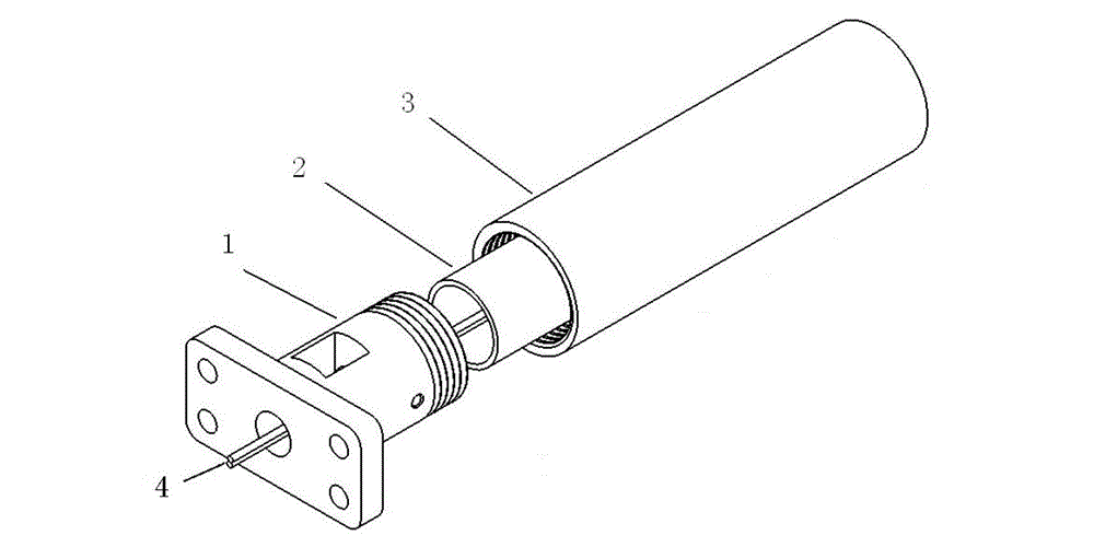
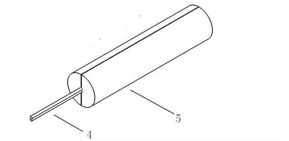
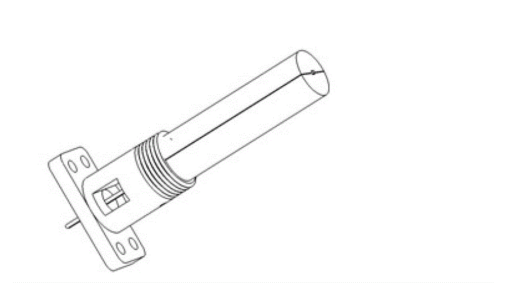
[0031] Embodiment 1, a kind of superconducting magnet joint, refer to figure 1 , including the joint seat 1 fixed on the seat plate and the copper sleeve 2 and the envelope 3 connected thereto, the two superconducting wires 4 are all niobium-three-tin superconducting wires 10 introduced from the lead hole on the end face of the joint seat 1, and welded to be superconducting Joint, between the copper sleeve 2 and the superconducting joint is potted Wood's alloy 7, see Figure 4 , two niobium-three-tin superconducting wires 10 are surrounded by Nb barrier layer 8, lead-bismuth conductor 9, Wood alloy 7 and copper sheath 2; the envelope 3 is connected to the joint seat 1 by threads, and is used to protect the superconducting joint 1 and shield the magnetic field ; In order to ensure high mechanical strength, the joint seat 1 and the envelope 3 are made of stainless steel, and in order to reduce the resistance of the superconducting joint, the copper sleeve 2 is made of oxygen-fre...

Embodiment 2

[0036] Embodiment 2, a kind of superconducting magnet joint, refer to figure 1 , including the joint base 1 fixed on the seat plate and the copper sleeve 2 and the envelope 3 connected thereto; in order to facilitate the production of superconducting joints when the materials of the two superconducting wires are different, the end surface and the side of the joint base 1 are respectively provided with lead holes. In this embodiment, the two superconducting wires 4 are a niobium-three-tin superconducting wire 10 and a niobium-titanium superconducting wire 6, which are respectively introduced and welded into superconducting joints from the lead holes on the end face and side of the joint base 1, see Figure 5 , the niobium-three-tin superconducting wire 10 and the niobium-titanium superconducting wire 6 are surrounded by a Nb barrier layer 8, a lead-bismuth conductor 9, Wood's alloy 7 and a copper sleeve 2; between the copper sleeve 2 and the superconducting joint is potted Wood'...


PUM

PropertyMeasurementUnit
Melting pointaaaaaaaaaa

Abstract

The invention discloses a superconducting magnet joint which comprises a joint holder and a copper sleeve connected to the joint holder, wherein a superconducting line passes through the joint holder and the copper sleeve and is welded into a superconducting joint, and a soldering flux is embedded between the copper sleeve and the superconducting joint. According to the invention, the outer layer of the superconducting line is plated with a lead-bismuth conductor and formed into the superconducting joint, and the welding length of the superconducting joint is not less than 75 mm, thereby ensuring that two superconducting line terminals connected with the superconducting joint have electric contact areas large enough so that the resistance of the joint can be effectively reduced. A wood alloy achieves complementing and strengthening effects, and the superconducting joint is fixed by using a high-conductivity oxygen-free copper sleeve, so that the resistance is further reduced. The superconducting joint is completed after heat treatment, so that the insulation damages of the superconducting joint in the process of heat treatment can be effectively avoided, and a greater degree of freedom is provided for the production and maintenance of the superconducting joint; and the superconducting joint is simple in production method and easy to operate.

Description

technical field [0001] The invention relates to a superconducting magnet joint, in particular to a superconducting magnet joint, and also relates to a manufacturing method of the superconducting magnet joint. Background technique [0002] Niobium tritin (Nb 3 Sn) has better advantages than niobium titanium (NbTi) in important parameters such as critical temperature, critical current and critical magnetic field. Nb 3 The critical temperature of Sn is about 18K, and the critical magnetic field strength reaches 28T at 4.2K. At the same background field and 4.2K temperature, Nb 3 The critical current density of Sn is three times that of NbTi. Therefore, Nb 3 Sn is a good material for making high-performance superconducting magnets, especially for high-field superconducting magnets. [0003] However, due to Nb 3 Sn is a compound-type brittle material, and any deformation or collision may damage its superconducting properties. Therefore, in actual engineering, winding Nb 3...

Claims


Application Information

Patent Timeline
IPC IPC(8): H01F6/06H01L39/00
Inventor 葛正福闫果梁书锦李超朱思华熊小伟杨世杰王彦平贾庆功冯勇
Owner 西安聚能医工科技有限公司
Learn More