Eureka AIR delivers breakthrough ideas for toughest innovation challenges, trusted by R&D personnel around the world.

Negative micropressure ignition system for sintering machine bellows

An ignition device and micro-negative pressure technology, applied in the field of micro-negative pressure ignition devices for sintering machine bellows, can solve problems affecting the production process, unstable sintering process, double-layer valve stuck, etc., to reduce energy consumption and production costs, The effect of reducing valve spare parts and maintenance costs and reducing gas consumption

Inactive Publication Date: 2012-10-10
LOUDI LINGYI MECHANICAL & ELECTRICAL EQUIP
View PDF6 Cites 7 Cited by
  • Summary
  • Abstract
  • Description
  • Claims
  • Application Information

AI Technical Summary

Problems solved by technology

[0003] ①The valve used is a double-layer valve. When the upper layer of the valve is opened, the lower layer will be closed. On the contrary, when the lower layer is opened, the upper layer will be closed. When there are many blanking materials on the sintering machine trolley, this double-layer valve will be stuck. , resulting in an unstable sintering process
[0004] ②The ignition device of this kind of tie-rod structure cannot (or does not) separate gas and matter, because the blanking on the sintering machine trolley and the exhaust air of the large flue are the same pipe, resulting in serious wear and tear of the double-layer valve and short service life , the maintenance (maintenance) cost is high, which directly affects the production process

Method used


Image

  • Negative micropressure ignition system for sintering machine bellows
  • Negative micropressure ignition system for sintering machine bellows
  • Negative micropressure ignition system for sintering machine bellows

Examples


Embodiment Construction

[0014] The specific implementation manners of the present invention will be further described in detail below in conjunction with the accompanying drawings.

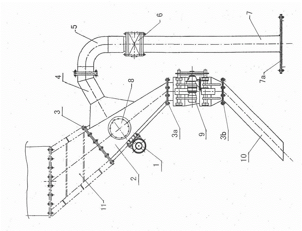
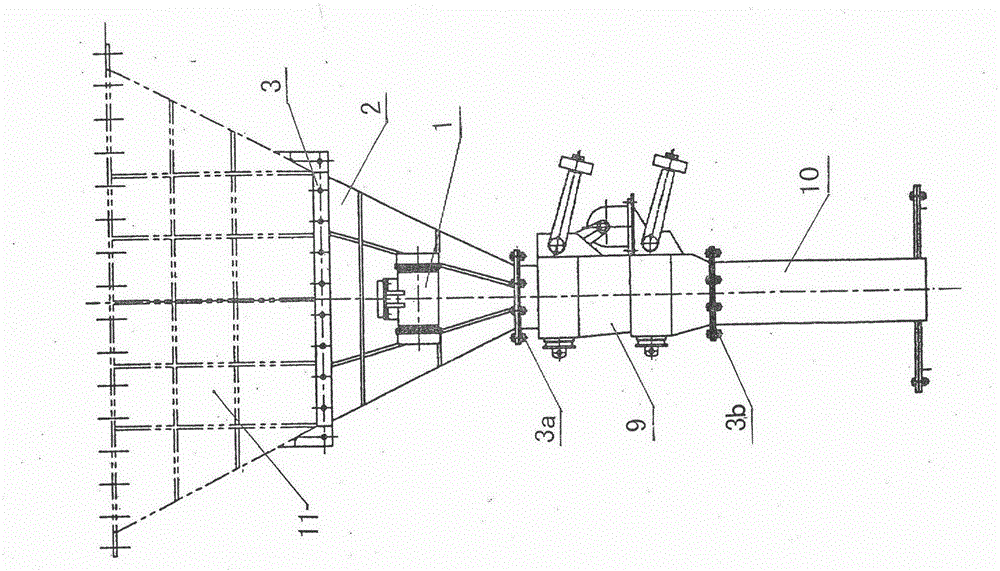
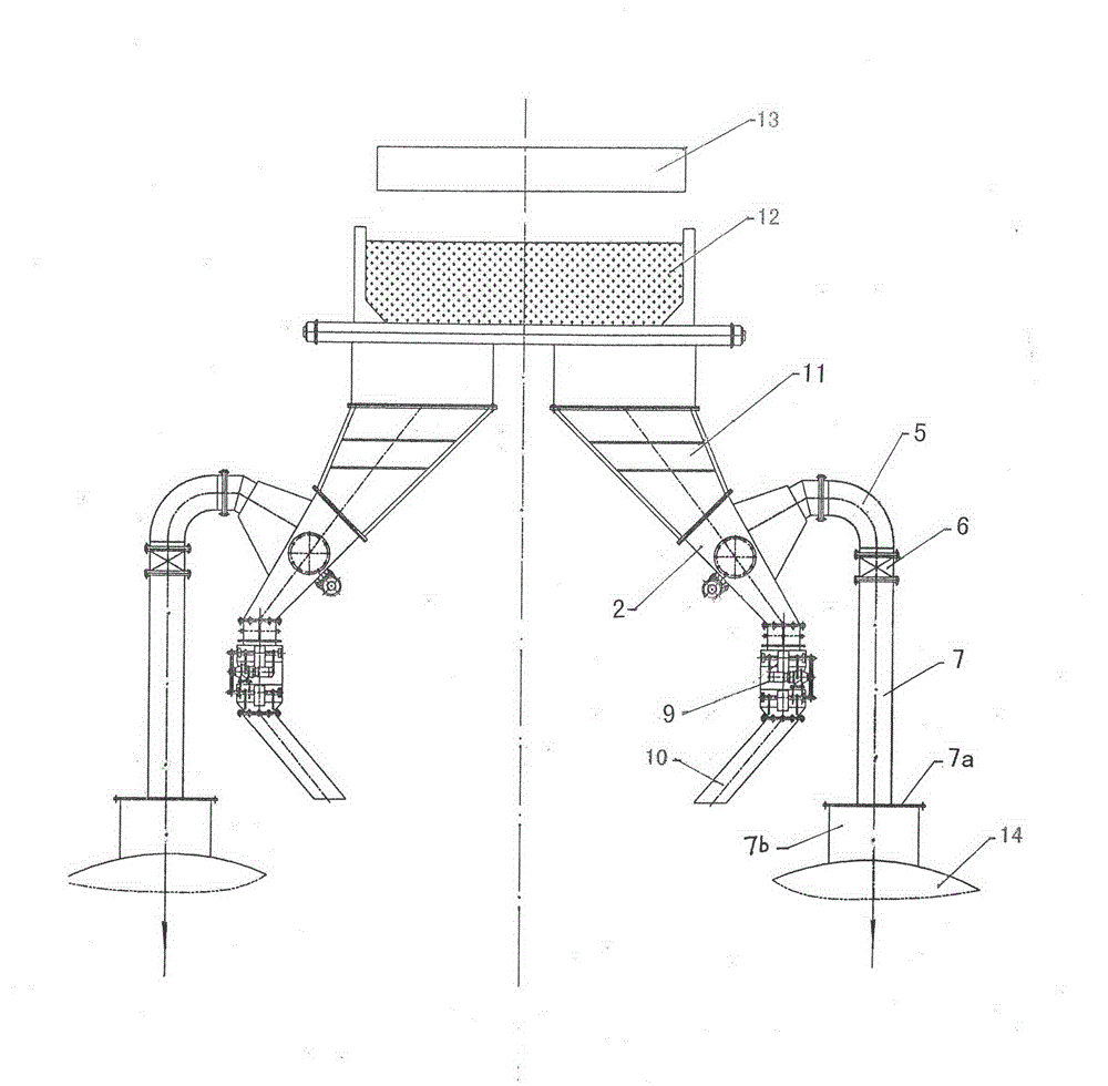
[0015] (As shown in the accompanying drawings) A sintering machine air box micro-negative pressure ignition device according to the present invention includes a vibration motor 1, an air box pipe 2, a first graphite packing 3, a second graphite packing 3a and a third graphite packing 3b, bellows wear-resistant pipe 4, wear-resistant elbow 5, resistance balance valve 6, vertical pipe 7, stuffy cover 7a, exhaust pipe 7b, observation hole cover 8, double-layer ash discharge valve 9, discharge pipe 10, bellows 11. The trolley 12 and the igniter 13, wherein the first graphite disc 3, the second graphite packing 3a and the third graphite packing 3b are high temperature resistant seals, which are available in the market, and the bellows pipe 2 has two ends Cylindrical or square barrels with equal or unequal cross-sectional dime...


PUM


Abstract

The invention discloses a negative micropressure ignition system for a sintering machine bellows. A trolley is located over the upper end of the bellows, an igniter is separately arranged over the top of the trolley, the upper part of the bellows is opposite to the lower end of the trolley via a duct, and the lower part of the bellows is connected with the upper part of a bellows pipe through a first graphite packing. A vibrating motor is mounted on one sidewall of the bellows pipe, an observation hole with an observation hole cover is arranged at the middle of the bellows pipe, the upper end of a double-layered cindervalve is connected with the lower end of the bellows pipe through a second graphite packing, and the lower end of the double-layered cindervalve is connected with a discharge pipe through a third graphite packing. A wear-resistant bellows-connecting pipe which communicates with the cavity of the bellows pipe is mounted on the other sidewall of the bellows pipe, and is connected with one end of a wear-resistant elbow through connecting flanges, the other end of the wear-resistant elbow is connected with the upper end of a vertical connecting pipe through a resistance balance valve, and the lower end of the vertical connecting pipe is connected with an axial air duct and a big flue through a cover. The negative micropressure ignition system can realize gas-material separation, effectively control the sintering thickness of sinter, increase the grade of sinter and reduce the production cost.

Description

technical field [0001] The invention relates to an ignition device, in particular to a micro-negative pressure ignition device for a sintering machine bellows used in the sintering process of providing high-quality sintered ore for ironmaking blast furnaces. Background technique [0002] As we all know, iron-containing fine ore cannot be directly put into the metallurgical blast furnace for ironmaking. It must go through the sintering process to turn the iron-containing fine ore into sintered ore before it can be put into the metallurgical blast furnace. In the sintering process of iron-containing powder ore, the sintering material is usually placed in the trolley, the igniter is placed at a certain interval above the trolley, and two symmetrical bellows are installed below the trolley. The lower end is connected with double-layer valves, and the operation of the two double-layer valves installed at the lower end of the bellows is controlled by an electric pull rod. The igni...

Claims


Application Information

Patent Timeline
IPC IPC(8): F27B21/08
Inventor 谭玲曾令勇
Owner LOUDI LINGYI MECHANICAL & ELECTRICAL EQUIP
Why Eureka
Eureka Blog
Learn More