
Automatic weighing and feeding device for electronic kiln

A technology of automatic weighing and feeding device, applied in the direction of automatic feeding/discharging weighing equipment, measuring device, furnace, etc. High investment cost and other issues

Inactive Publication Date: 2014-02-26
常州力诺电子衡器有限公司
View PDF4 Cites 12 Cited by
  • Summary
  • Abstract
  • Description
  • Claims
  • Application Information

AI Technical Summary

Problems solved by technology

[0003] In the prior art, the automatic weighing and feeding device commonly used in the industry before the present application has the defect that it cannot be well connected with the aforementioned conveying device. Yes: There is a waiting process after the transport device transports the empty trays to the automatic weighing and feeding device. The so-called waiting process refers to the process of waiting for the automatic weighing and feeding device to weigh, thus affecting the material transportation Continuity of movement of the device
The current solution is to equip a set of material transport device with two or more automatic weighing and feeding devices. However, although this measure can meet the fast material transport requirements of the material transport device, there are the following technical problems: one, causing The investment in equipment is large, the investment cost is high, and the degree of equipment management and maintenance is large; secondly, due to the existence of multiple automatic weighing and feeding devices, it is bound to increase the complexity of the structure of the feeding device, because the feeding device needs to meet the needs of different customers at the same time. The position of the automatic weighing feeding device to pick up materials; third, it takes up a lot of space for the production site

Method used


Image

  • Automatic weighing and feeding device for electronic kiln

Examples


Embodiment Construction

[0015] In order to enable the examiners of the patent office, especially the public, to understand the technical essence and beneficial effects of the present invention more clearly, the applicant will describe in detail the following in the form of examples, but none of the descriptions of the examples is an explanation of the solutions of the present invention. Any equivalent transformation made according to the concept of the present invention which is merely formal but not substantive shall be regarded as the scope of the technical solution of the present invention.

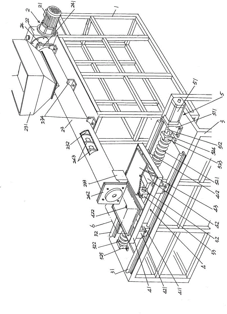
[0016] See figure 1 , a frame-type material feeding frame 1 is provided, an automatic feeding mechanism 2 is arranged on the top of the feeding frame 1, and the automatic feeding mechanism 2 includes a first motor 21, a worm gear reducer 22, a screw The feeding pipe 23 and the screw shaft 24, the first motor 21 is connected with the worm gear reduction box 22 in a horizontal lying state, and is fixed on ...


PUM


Abstract

The invention relates to an automatic weighing and feeding device for an electronic kiln, belonging to the technical field of the supporting facilities of electronic kilns. The automatic weighing and feeding device comprises a material conveying rack, an automatic material conveying mechanism, a metering rack, a weighing mechanism and a weighing disk moving mechanism, wherein the automatic material conveying mechanism is arranged at the top of the material conveying rack, the metering rack is arranged at one end of the material conveying rack, a first guide rail is fixedly arranged at one side of the top of the metering rack in the length direction, a second guide rail is fixedly arranged at the other side of the top of the metering rack in the length direction, the weighing mechanism is matched with the first guide rail and the second guide rail in a sliding manner and also corresponds to the automatic material conveying mechanism, and the weighing disk moving mechanism is arranged on the metering rack and is in transmission connection with the weighing mechanism. The automatic weighing and feeding device for the electronic kiln has the advantages that the requirements of uninterrupted weighing and metering are met by only one device, and then, the material conveying mechanism is guaranteed to uninterruptedly take materials, so that the design and the investment can be saved, the difficulty in the management and the maintenance of the device can be reduced, the efficiency can be increased, and the occupied space of a production site can be saved.

Description

technical field [0001] The invention belongs to the technical field of supporting facilities for electronic kilns, and in particular relates to an automatic weighing and feeding device for electronic kilns, which is used for supplying weighed materials to automatic feeding devices for electronic kilns, and the electronic kilns automatically transport materials The unit is transported to the setter of the electric kiln. Background technique [0002] The electronic kiln mentioned above is used for firing powder materials for electronic components such as colored phosphor powder, lamp powder, barium titanate, strontium titanate, yttrium oxide, titanium dioxide, zirconium oxide, aluminum oxide, bismuth oxide , lead zirconate titanate, lithium iron phosphate or ferrite magnetic powder, etc. These materials are not limited to the examples listed, and usually need to be transported by the electronic kiln automatic feeding device (referred to as the feeding device) to the setter bo...

Claims


Application Information

Patent Timeline
Patent Type & Authority Patents(China)
IPC IPC(8): F27D3/00G01G13/24
Inventor 李巍刘向蕾尹伊张廷威
Owner 常州力诺电子衡器有限公司
Learn More