
Separator for non-aqueous electrolyte secondary battery and non-aqueous electrolyte secondary battery using the same

A non-aqueous electrolyte and secondary battery technology, which is applied in the direction of non-aqueous electrolyte batteries, separators/films/diaphragms/spacer components, battery components, etc. Problems such as clogging and operability decline, etc., to achieve a good capacity maintenance effect

Active Publication Date: 2012-09-26
PANASONIC CORP
View PDF8 Cites 19 Cited by
  • Summary
  • Abstract
  • Description
  • Claims
  • Application Information

AI Technical Summary

Problems solved by technology

However, to meet such requirements, if the pore diameter of the separator is simply increased, an internal short circuit due to the growth of needle-shaped lithium metal (dendrite) will easily occur.
Furthermore, if the dendrites are free, it will cause a drop in battery capacity or blockage of the separator.
In addition, if the porosity is simply increased, the tensile strength and puncture strength of the separator will decrease, or the handleability will decrease.

Method used


Image

  • Separator for non-aqueous electrolyte secondary battery and non-aqueous electrolyte secondary battery using the same
  • Separator for non-aqueous electrolyte secondary battery and non-aqueous electrolyte secondary battery using the same
  • Separator for non-aqueous electrolyte secondary battery and non-aqueous electrolyte secondary battery using the same

Examples


Embodiment 1)

[0124] (1) Fabrication of positive electrode 5

[0125] In an appropriate amount of N-methyl-2-pyrrolidone, 100 parts by mass of lithium cobaltate as a positive electrode active material, 2 parts by mass of acetylene black as a conductive agent, and 3 parts by mass of polyvinylidene fluoride resin as a binder are added and Kneading is carried out to prepare a slurry-like mixture. This slurry was continuously applied to both surfaces of a strip-shaped aluminum foil (thickness: 15 μm) serving as a positive electrode current collector. Among them, the exposed part of the aluminum foil for connecting the positive electrode lead 5a was left. The coating film of the dried mixture is rolled together with the positive electrode current collector under a linear pressure of 1000kgf / cm (9.8kN / cm) for 2 to 3 times, and the thickness of the coating film is adjusted to 180μm to make a positive electrode active material Floor. Then, the current collector having the positive electrode acti...

Embodiment 2)

[0151] A battery was produced in the same manner as in Example 1 except for using the separator described below.

[0152] First, various polyethylene porous membranes with an average distance between extended chain crystals of 3.0 μm or more and less than 5.0 μm and an average distance between folded chain crystals of 0.5 μm or more but less than 0.7 μm were prepared (compared to Table 1). No.6 same structure). The thickness of the polyethylene porous membrane was set to 20 μm or 17 μm. For a polyethylene porous membrane with a thickness of 20 μm, various polyethylene porous membranes are produced by appropriately changing the conditions of the manufacturing process so that they have the same structure as No. 6 in Table 1, and the final Glyer air permeability and porosity changes.

[0153] In addition, an NMP solution of aramid was coated on one side of a polyethylene porous membrane having a thickness of 17 μm. Thus, a separator having a two-layer structure of a polyethyle...


PUM

PropertyMeasurementUnit
linear shrinkageaaaaaaaaaa
apparent porosityaaaaaaaaaa
linear shrinkageaaaaaaaaaa

Abstract

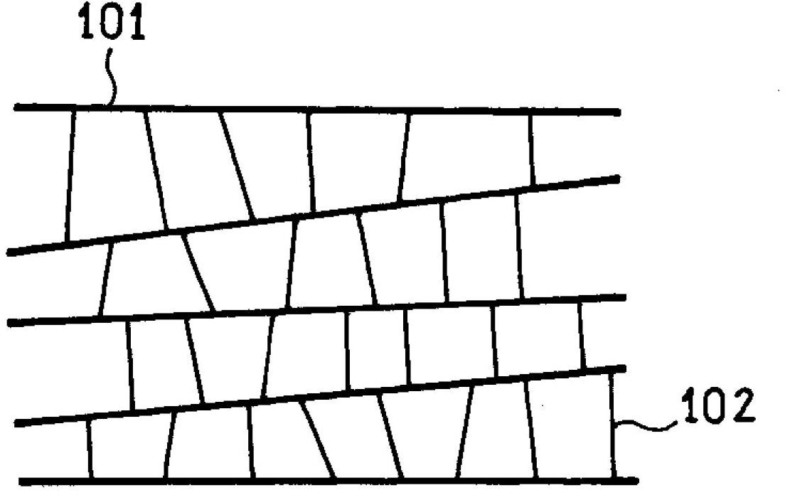
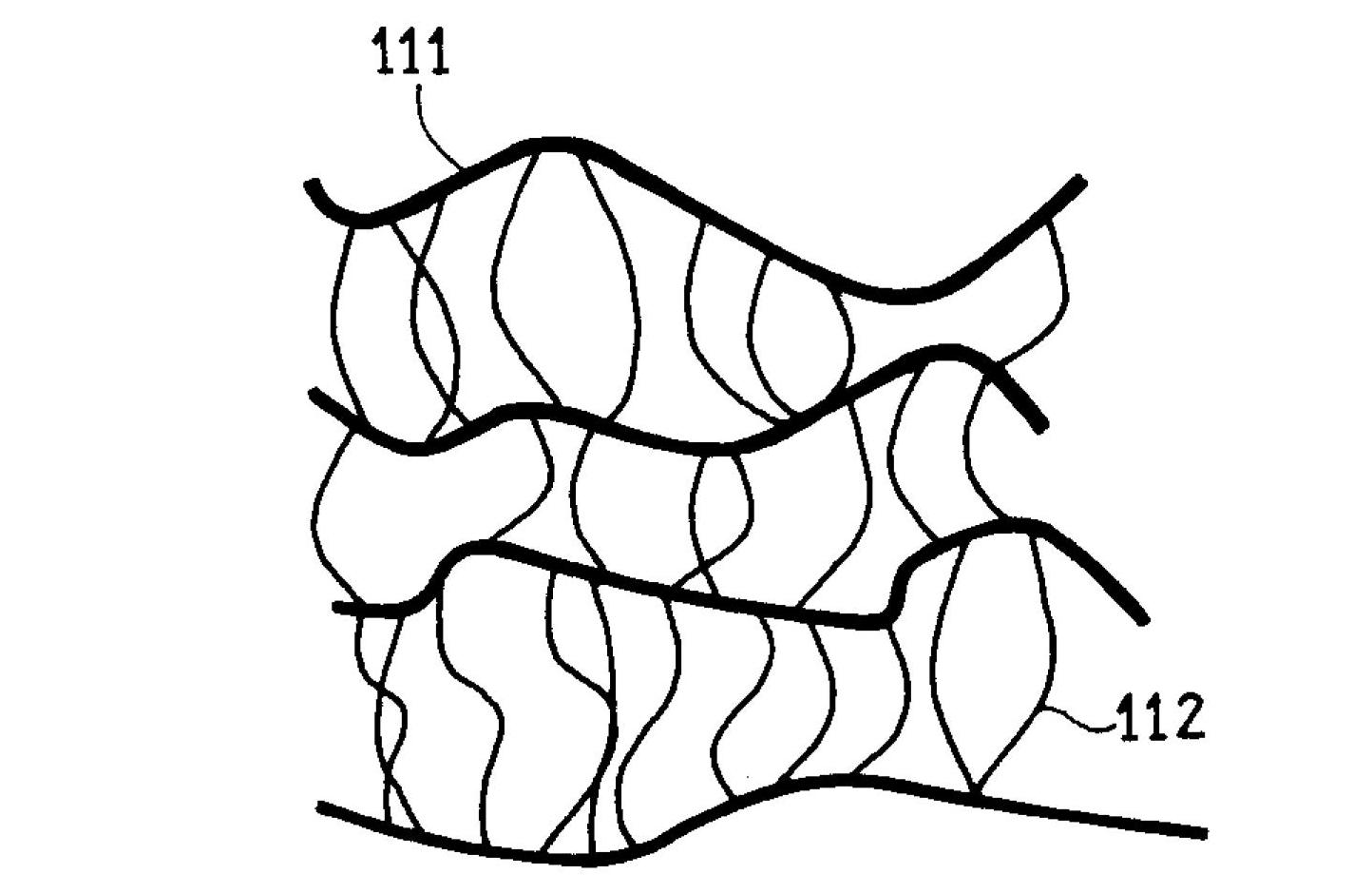
This separator for a non-aqueous electrolyte secondary battery contains a biaxially oriented polyolefin porous membrane containing extended-chain crystals and folded-chain crystals; the extended-chain crystals and folded-chain crystals form a shish-kebab structure; the average distance between adjacent extended-chain crystals is at least 1.5 [mu]m and less than 11 [mu]m; and the average distance between adjacent folded-chain crystals is at least 0.3 [mu]m and less than 0.9 [mu]m. A heat-resistant porous membrane may be laminated to the polyolefin porous membrane. The heat-resistant porous membrane contains a resin having heat resistance or a higher melting point than the melting point of the polyolefin porous membrane.

Description

technical field [0001] The present invention relates to an improvement of a separator for a non-aqueous electrolyte secondary battery including a polyolefin porous film, and further relates to a non-aqueous electrolyte secondary battery capable of improving the capacity retention rate in a charge-discharge cycle of rapid charging. Background technique [0002] In recent years, the mobility and cordlessness of electronic devices are rapidly advancing. As a power source for driving these devices, a small consumer secondary battery that is small in size and light in weight and has high energy density is generally used. In addition, large-scale secondary batteries have also been developed as power storage devices and power sources for driving electric vehicles. These secondary batteries are required to have characteristics such as high output characteristics, long-term durability, and safety. Therefore, the development of non-aqueous electrolyte secondary batteries having high...

Claims


Application Information

Patent Timeline
Patent Type & Authority Applications(China)
IPC IPC(8): H01M2/16H01M10/05H01M50/417H01M50/443H01M50/451H01M50/489H01M50/491
CPCH01M10/05Y02E60/12H01M2/16Y02E60/10H01M50/44H01M50/417H01M50/451H01M50/491H01M50/443H01M50/489
Inventor 中桐康司柴野靖幸山本典博
Owner PANASONIC CORP
Learn More