Method for manufacturing sponge iron

A manufacturing method and technology of sponge iron, applied in the direction of fluidized bed furnace, etc., can solve the problems of low production efficiency, low product density, uneven reaction, etc., and achieve the effect of reducing metal recovery rate, reducing material loss, and prolonging smelting time

Inactive Publication Date: 2012-09-19
SHANXI YINGZHIJIE MATERIAL
View PDF4 Cites 6 Cited by
  • Summary
  • Abstract
  • Description
  • Claims
  • Application Information

AI Technical Summary

Problems solved by technology

During the reaction process of this process, the iron-containing raw materials and the reducing agent are relatively static, and the mass and heat transfer process is poor, resulting in long reaction time, uneven and incomplete reaction, low product density, and low metallization rate. Industrial waste includes waste tanks, waste reduction Desulfurization agent, desulfurization agent, large amount of production, complicated process and other defects
[0003] At present, both at home and abroad, the rotary kiln method is used in the reduction process, and they all hold a negative attitude. Yang Tianjun pointed out on page 251 of "Smelting Reduction" that "this kind of process equipment is huge, has extremely high requirements on ore and coal types, and has low production efficiency." Seamless, Miyun Mining and Metallurgical Company, Shandong Luzhong and other enterprises are examples of unsatisfactory production of sponge by rotary kiln process

Method used


Image

  • Method for manufacturing sponge iron
  • Method for manufacturing sponge iron
  • Method for manufacturing sponge iron

Examples


Embodiment 1

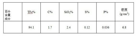
[0011] Dry iron concentrate powder, blue charcoal powder, lime powder and ferrosilicon powder respectively and crush them to 50 meshes, mix them according to weight percentage 1: 0.2: 0.1: 0.05, put them into a rotary kiln, heat up to 1150°C for 80 minutes, Keep the temperature out of the kiln for 8 hours and take out the sponge iron.

[0012]

Embodiment 2

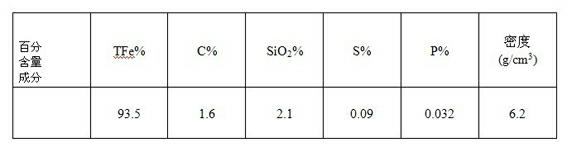
[0014] Dry and crush iron-containing dust, blue carbon powder, lime powder, and ferrosilicon powder to 80 meshes, mix them according to weight percentage 1: 0.4: 0.2: 0.1, put them into a rotary kiln, and heat up to 1200°C for 100 minutes. Keep the temperature out of the kiln for 10 hours and take out the sponge iron.

[0015]

Embodiment 3

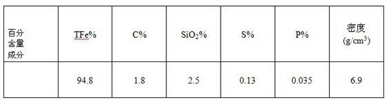
[0017] Dry the gravity dust removal powder, blue charcoal powder, lime powder and ferrosilicon powder respectively, crush them to 100 mesh, mix them according to the weight percentage 1: 0.6: 0.3: 0.15, put them into the rotary kiln, raise the temperature for 120 minutes to 1250°C, and keep the temperature constant 12 hours out of the kiln to take out the sponge iron.

[0018]


PUM

PropertyMeasurementUnit
densityaaaaaaaaaa
densityaaaaaaaaaa

Abstract

The invention relates to a method for manufacturing sponge iron. The method for manufacturing sponge iron comprises the following steps of: respectively drying and crushing a ferric oxide, a reducing agent, a desulfurizing agent, an activating agent to 50-100 meshes, mixing the raw materials according to a weight ratio being 1:(0.2-0.6):(0.1-0.3):(0.05-0.15), adding the mixture to a kiln body to carry out a reduction reaction, and cooling down to produce sponge iron products. The ferric oxide is any one of iron concentrate powder, iron-containing dust slime, phosphorus iron oxide and gravitational dust-removed powder, wherein the reducing agent is one of low-sulfur coal, coke powder and blue powdered carbon, the desulfurizing agent is lime powder, and the activating agent is silicon iron powder; the heating time is controlled within 8-12h, the heating temperature is within 1,000-1,250 DEG C, and the density of the sponge body products is 6-7g/cm<3>. The method for manufacturing sponge iron, disclosed by the invention, has the advantages of improving conditions of mass transfer and heat transfer, creates more beneficial conditions for chemical reactions; the activating agent has double functions of reduction and catalysis; the complicated front-stage in-kiln process and post-stage cooling drawing process in the traditional technique are improved; industrial refuse are reduced by more than 50% as compared with that generated by an original process.

Description

technical field [0001] The invention relates to a method for manufacturing sponge iron, which is mainly aimed at the method for producing sponge iron by heating and reducing iron-based oxides. Background technique [0002] The traditional tunnel kiln sponge iron production process is to mix coke powder or low-sulfur coal, desulfurization agent or lime powder, layer with iron-containing oxides and put them into refractory tanks, and then enter the kiln at a temperature of 1100-1200°C and heat for 40-50 Hours for reduction reaction, after cooling out of the kiln out of the tank to obtain sponge iron products. During the reaction process of this process, the iron-containing raw material and the reducing agent are relatively static, and the mass transfer and heat transfer process is poor, resulting in long reaction time, uneven reaction, incomplete reaction, low product density, low metallization rate, and industrial waste including waste tanks and waste reduction. Desulfurizat...

Claims


Application Information

Patent Timeline
Patent Type & Authority Applications(China)
IPC IPC(8): C21B13/00
Inventor 张和起张立伟张立德
Owner SHANXI YINGZHIJIE MATERIAL
Why Eureka
Try Eureka