Light-emitting diode (LED) fluorescent diaphragm and LED illuminating lamp based on LED florescent diaphragm

A technology of LED chip and fluorescent film, which is applied in the field of LED lighting fixtures, can solve the problems of limited LED light luminous efficiency, LED failure to emit light, loss of lighting or display functions, etc., to protect eyesight, improve color rendering quality, high The effect of luminous efficiency

Inactive Publication Date: 2012-08-22
XIAMEN QUANTUM STAR TECH
View PDF4 Cites 8 Cited by
  • Summary
  • Abstract
  • Description
  • Claims
  • Application Information

AI Technical Summary

Problems solved by technology

With the increasing application of high-power chips, this direct dispensing phosphor layer process will lead to increasingly serious heat dissipation problems for LED lamps. The heat is directly transmitted to the phosphor layer coated by dispensing, causing the organic adhesive material to degrade and age due to heat. Gradually darkening the color directly affects the light output rate and limits the luminous efficiency of the LED lamp. When the aging is serious, it may even cause the entire LED to fail to emit light and lose its lighting or display function.

Method used


Image

  • Light-emitting diode (LED) fluorescent diaphragm and LED illuminating lamp based on LED florescent diaphragm
  • Light-emitting diode (LED) fluorescent diaphragm and LED illuminating lamp based on LED florescent diaphragm
  • Light-emitting diode (LED) fluorescent diaphragm and LED illuminating lamp based on LED florescent diaphragm

Examples


Embodiment 1

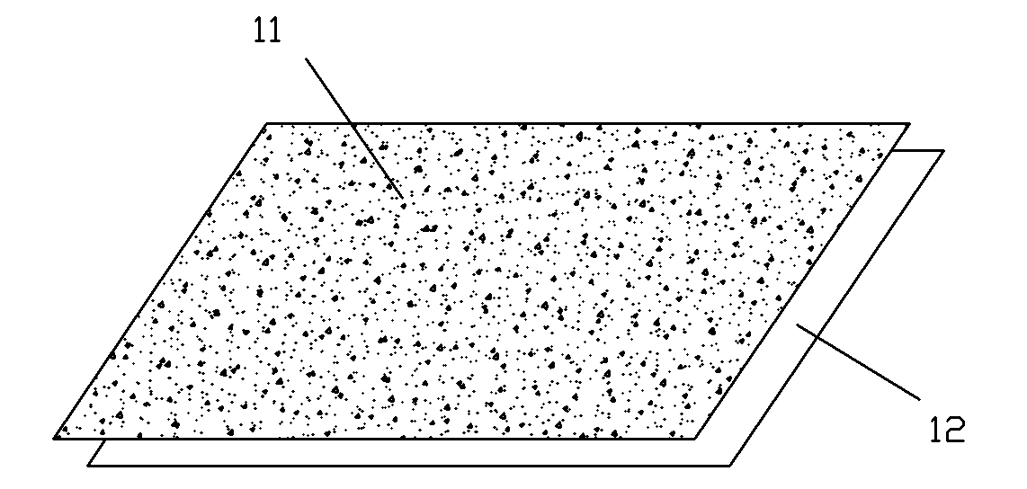
[0030] Embodiment one, see figure 1As shown, a LED fluorescent film of the present invention is composed of a fluorescent film layer 11, and the production of the fluorescent film layer 11 is formed by firstly mixing transparent colloids such as epoxy resin, silicone resin or ink and fluorescent powder raw materials uniformly. Phosphor powder colloid, and then use the printing process to uniformly print the phosphor powder colloid on the support mold 12, and finally remove it from the support mold after heating and drying or drying at room temperature;

[0031] Wherein, the phosphor raw material is one or two of yellow YAG phosphor, yellow TAG phosphor, green aluminate phosphor, red silicate phosphor or red nitride phosphor;

[0032] The weight ratio of phosphor raw materials is 10% to 90%;

[0033] 10% to 90% by weight of epoxy resin, silicone resin or ink;

[0034] The thickness of the fluorescent film layer is 0.1 mm to 3 mm.

[0035] The shape of the fluorescent film la...

Embodiment 2

[0038] Embodiment two, see figure 2 As shown, a LED fluorescent film of the present invention is composed of a fluorescent film layer 21 and a thin supporting light-transmitting film 22, and the fluorescent film layer 21 is made on the supporting light-transmitting film 22 by pasting; The production of fluorescent film layer 21 is to firstly mix transparent colloids such as epoxy resin, silicone resin or ink with fluorescent powder raw materials to form fluorescent powder colloids, and then use printing technology to evenly print phosphor powder colloids on the supporting light-transmitting film 22 , and finally made on the supporting light-transmitting film 22 after heating and drying or drying at room temperature;

[0039] Wherein, the phosphor raw material is one or two of yellow YAG phosphor, yellow TAG phosphor, green aluminate phosphor, red silicate phosphor or red nitride phosphor;

[0040] The weight ratio of phosphor raw materials is 10% to 90%;

[0041] 10% to 90%...

Embodiment 3

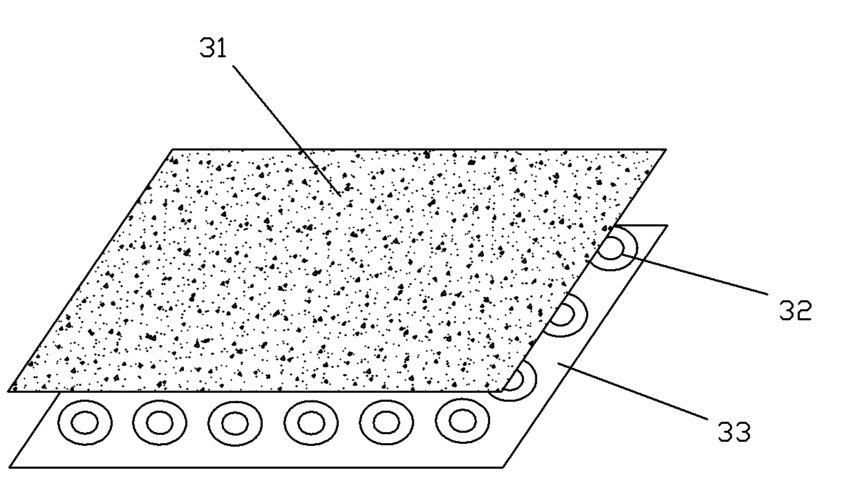
[0046] Embodiment three, see image 3 As shown, a LED lighting fixture based on the above-mentioned LED fluorescent film of the present invention includes an LED fluorescent film 31 and a lamp support frame 33 (a schematic diagram) equipped with a blue LED chip or an ultraviolet LED chip 32; the LED The fluorescent film 31 is covered and fixed on a fixed or adjustable spacing lamp support frame 33 at a certain distance, and there is a preset between the bottom end surface of the LED fluorescent film 31 and the upper end surface of the blue LED chip or the ultraviolet LED chip 32. cavities with a certain distance.

[0047] Wherein, the LED fluorescent film 31 may be the LED fluorescent film produced in the first embodiment, or the LED fluorescent film produced in the second embodiment.

[0048] The invention can produce LED lighting fixtures of various geometric shapes.

[0049] According to user's preferences and different purposes, the present invention can select different...


PUM


Abstract

The invention discloses a light-emitting diode (LED) fluorescent diaphragm and an LED illuminating lamp based on the LED florescent diaphragm. The LED fluorescent diaphragm consists of a fluorescent film layer and a supporting transparent diaphragm. The fluorescent film layer is produced through the following steps of: firstly and evenly mixing adhesive with fluorescent powder raw materials to form fluorescent powder colloids, then adopting a printing technology to evenly print the fluorescent powder colloids on a supporting mold or the supporting transparent diaphragm and finally heating and drying or air-drying at room temperature. The LED illuminating lamp is produced through the following steps of: covering and fixing the LED fluorescent diaphragm on a lamp support and reserving a fixed or adjustable cavity with certain distance between the LED fluorescent diaphragm and a chip. The LED illuminating lamp has the advantages that the heat produced when the chip is on and light is emitted is prevented from being directly transferred to the fluorescent film layer, the organic material of the fluorescent powder film layer is enabled not to be heated, degraded or aged on the whole, the LED light out-coupling efficiency is not influenced, the high luminous efficiency of the LED can be kept for a long time, the goals of high efficiency, energy saving and long service life of the illuminating lamp are realized and the illuminating lamp can display patterns and characters.

Description

technical field [0001] The invention relates to an LED lighting fixture, in particular to an LED fluorescent membrane and an LED lighting fixture based on the LED fluorescent membrane. Background technique [0002] In 1993, Japan’s Nichia Chemical Company took the lead in making a breakthrough in blue gallium nitride LED technology and quickly industrialized it. In 1996, it developed a yellow light series of yttrium aluminum garnet phosphors combined with blue light-emitting diodes as a high-efficiency white light source. . It was introduced to the market in 1998 and found a new lighting stage for LEDs. White LEDs have developed rapidly and have shown good application prospects in the field of general lighting. The blue light or ultraviolet light emitted by the semiconductor compound chip belongs to p-n junction electroluminescence, while the yellow light emitted by the phosphor realizes the light energy conversion of blue light to yellow light, which is a typical down-conv...

Claims


Application Information

Patent Timeline
Patent Type & Authority Applications(China)
IPC IPC(8): F21V9/10F21V17/00F21S2/00F21Y101/02F21V9/40F21K9/20F21K9/64F21Y115/10
Inventor 熊春花熊逸
Owner XIAMEN QUANTUM STAR TECH
Why Eureka
Try Eureka