
Utilization device for spiral internal air energy

A technology of air internal energy and exhaust device, applied in jet propulsion device, gas turbine device, machine/engine, etc., can solve the problem of limited effective enthalpy drop and thermal efficiency improvement, no major breakthrough in thermal engine efficiency, and can not reach the average heat absorption Problems such as temperature corresponding to pressure ratio

Inactive Publication Date: 2012-08-15
杜臣
View PDF8 Cites 2 Cited by
  • Summary
  • Abstract
  • Description
  • Claims
  • Application Information

AI Technical Summary

Problems solved by technology

In addition, research and inventions in this area are often referred to as the first or second type of perpetual motion machines, which hinders the research and application of air internal energy utilization.
[0004] The theoretical system supporting the heat engine is thermodynamics and the Carnot heat engine cycle theory; the Carnot heat engine cycle theory points out the direction for people to improve the efficiency of the heat engine, and at the same time closes the door for people to use the internal energy of matter; the Carnot cycle can be expressed as: "The heat engine must be at least Work between two heat sources, absorb heat from the high-temperature heat source, and transfer part of it to the low-temperature heat source, so as to obtain mechanical work "" that is, work on the same high-temperature heat source T 1 and low temperature heat source T 2 The efficiency of a reversible Carnot engine for everything in between: "(Extracted from pages 223 and 226 of "Thermal Science" edited by Wu Bidong and Si Songle, Shanghai Science and Technology Press in 1983); currently used heat engines all use the environment as a low-temperature heat source; people cannot change the ambient temperature. According to Carnot theory, Therefore, the average endothermic temperature should be increased as much as possible, but the increase in heat engine efficiency is far from the theoretical value. It is found that there is a corresponding pressure ratio relative to the average endothermic temperature, and the corresponding pressure ratio of the average endothermic temperature restricts the level of effective enthalpy drop and heat engine efficiency. , so the pressure of the medium is increased as much as possible, but at the same time as the pressure ratio increases, the average endothermic temperature will also increase correspondingly, and the corresponding pressure ratio of the average endothermic temperature is always not reached, and the effective enthalpy drop and thermal efficiency increase are very limited; nearly People have been wandering in this vicious circle for half a century, and there has been no major breakthrough in the efficiency of heat engines

Method used


Image

  • Utilization device for spiral internal air energy
  • Utilization device for spiral internal air energy
  • Utilization device for spiral internal air energy

Examples


specific Embodiment approach 1

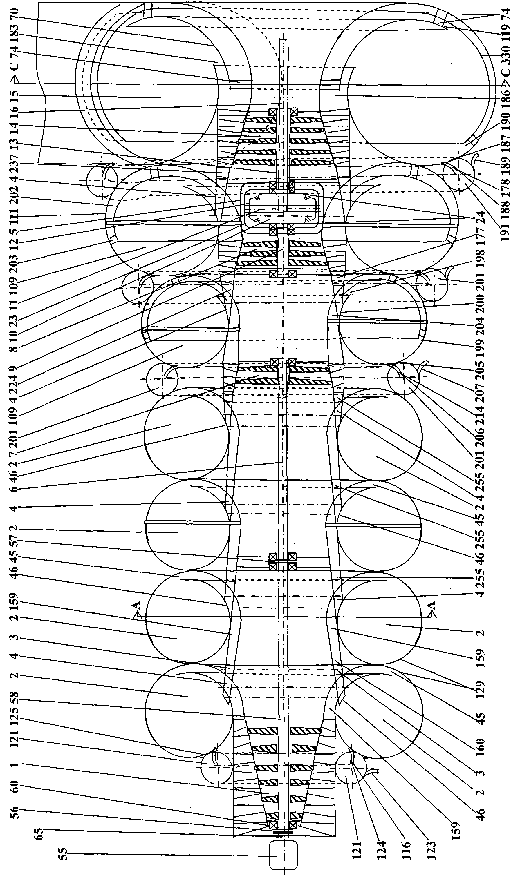
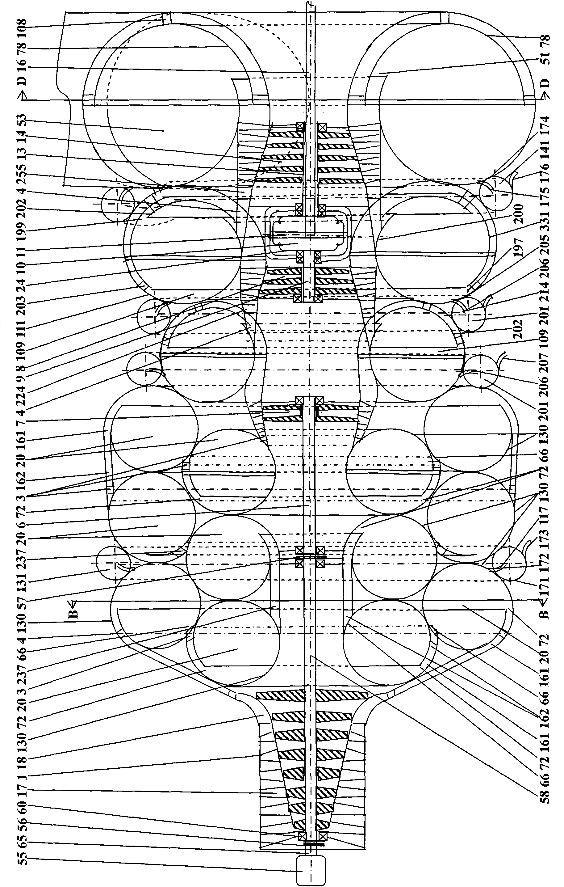
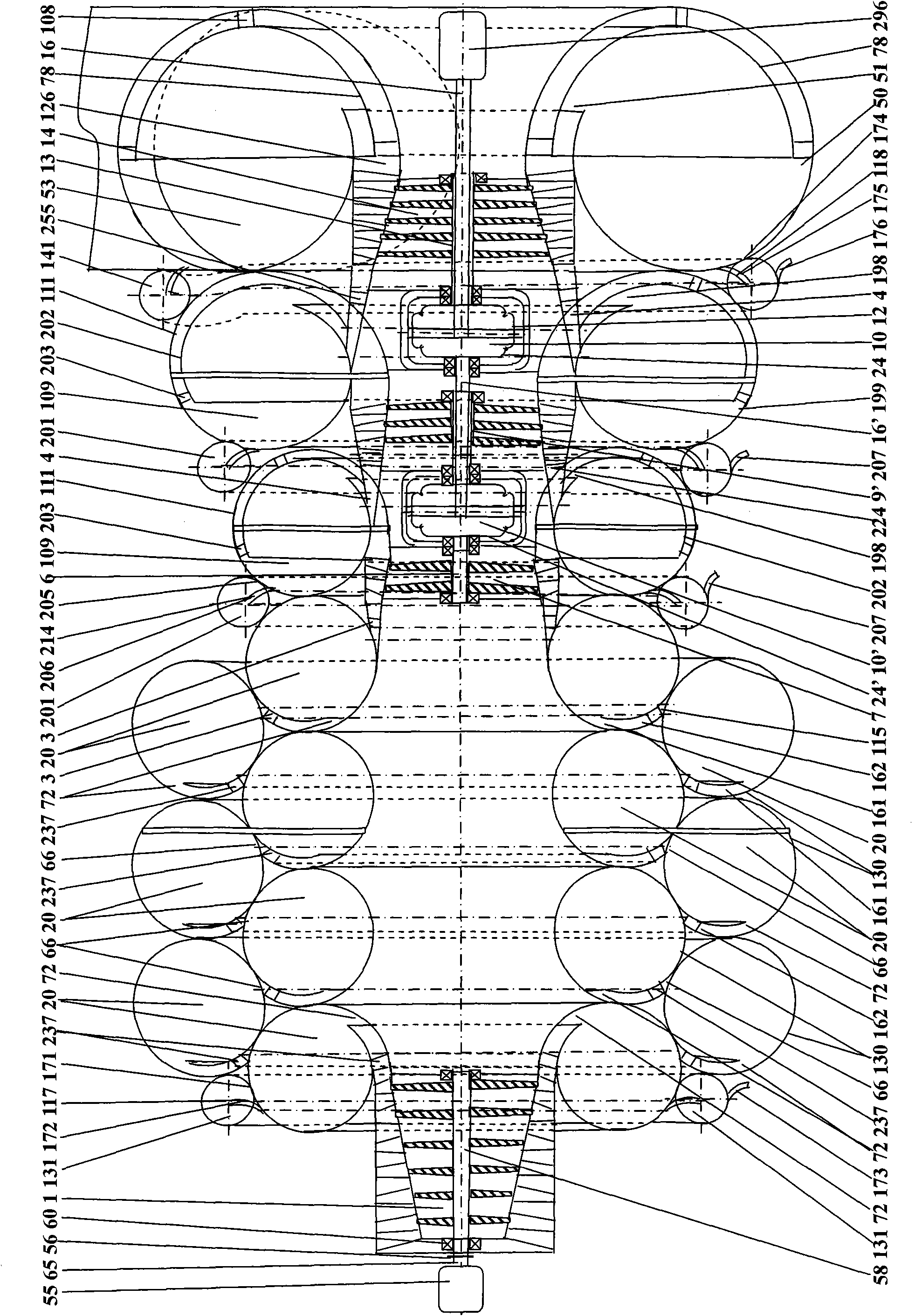
[0016] Specific implementation mode one, combining Figure 1 to Figure 27Describe this embodiment, the vortex air internal energy utilization device of this embodiment includes starter 55, starter clutch 56, compressor 1, ratchet type overrunning clutch 57, bushing type differential coupling, high pressure turbine 7, Medium-pressure turbine 8, low-pressure turbine 14 and computer control center; it is characterized in that: the energy utilization device in the vortex air also includes a vortex supercharger, a vortex exhaust device, a wedge control device; the vortex The turbocharger is composed of the first group of series-connected multi-stage scroll turbochargers arranged between the compressor 1 and the high-pressure turbine 7, and the second group of series-connected multi-stage turbochargers arranged between the high-pressure turbine 7 and the medium-pressure turbine 8. The scroll supercharger and the third group of series-connected multi-stage scroll superchargers arrang...

specific Embodiment approach 2

[0019] Specific implementation mode two: combination Figure 1 to Figure 4 , Figure 13 to Figure 15 Illustrate this specific embodiment, the wedge-shaped body regulating device of this specific embodiment is a one-position variant wedge-shaped body regulating device 224; Control device runner 226, at least three one-position variable wedge control device slideways 227 and the same number of one-position variable wedge control device rack chute 228, one-position variable wedge control device gear 229, one The gear shaft 230 of the position-variable wedge regulating device is composed of; the flow path 226 of the one-position variable wedge regulating device is a tapered or gradually expanding annular airflow passage, and at least three one-position variable wedge regulating device slides 227 are installed on On the inner wall of the channel 226 of the one-position variable wedge control device parallel to the axis, two adjacent one-position variable wedge control device slide...

specific Embodiment approach 3

[0021] Specific implementation mode three: combination Figure 1 to Figure 4 , Figure 16 and Figure 17 Illustrate this specific embodiment, the wedge-shaped body regulating device of this specific embodiment is the extrapolation deformed wedge-shaped body regulating device 237; Extrapolation deformed wedge body 238, two first bar irons 244, at least two extrapolated deformed wedge regulating device gear shafts 243, at least four extrapolated deformed wedge regulating device gears 242 and the same number of outer The push-out deformation wedge control device rack chute 241 and the external push-out wedge control device slideway 240 are formed; each external push-out wedge 238 is made up of at least two strip-shaped elastic steel plates, and the two outer One end of the push-out deformed wedge 238 is fixedly installed on the corresponding two walls of the flow channel 239 of the push-out deformed wedge control device respectively, and the push-out deformed wedge control devi...


PUM


Abstract

The invention relates to a utilization device for spiral internal air energy, which belongs to the field of renewable energy source and machinery manufacture. The situation that internal air energy is divided into forbidden zones by thermodynamics is a blank by application. Multistage vortex superchargers are respectively connected in series between the compressor of the device and a high-pressure turbine as well as among a high-pressure turbine, a middle-pressure turbine and a low-pressure turbine; the air inlet channel and the air outlet pipeline of each vortex supercharger are respectively provided with a wedge-shaped body regulation device; a high-pressure turbine shaft is in driving connection with a compressor shaft by a ratchet type overrunning clutch; the middle-pressure turbine and the low-pressure turbine shaft are in differential connection by a sleeve type differential coupler and output power by one shaft; under the eddy current field effect, potential flow superposition and the Rafael spray pipe clinical effect action, the vortex supercharger and a vortex exhaust device utilize the internal energy of medium to dynamically compress to lift medium pressure; the conversion of the internal energy to dynamic energy, the dynamic energy to the potential energy and the potential energy to the mechanical energy of the internal medium parts including air is realized to simultaneously produce cold quantity and fresh water. The utilization device is especially suitable for the occasions with refrigeration and fresh water requirement while distributed power generation.

Description

technical field [0001] The invention relates to the technical field of renewable energy utilization and mechanical manufacturing, in particular to a vortex air internal energy utilization device which converts air internal energy into mechanical energy, and refrigerates and produces water as by-products. Background technique [0002] With the development of modern economy and society, the demand for energy is increasing, and the energy structure is dominated by non-renewable and highly polluting petrochemical energy; the overall effect of petrochemical energy use is to warm the earth, and its main emission is carbon dioxide, which hinders the spread of the earth's heat to the outer space. Radiation, average temperature rise and pollution have destroyed the natural ecological environment of the earth, and the consequences are disastrous; the use of renewable energy has made some progress in recent years, but there are still many problems to be solved, such as large investment,...

Claims


Application Information

Patent Timeline
Patent Type & Authority Applications(China)
IPC IPC(8): F02C3/04F02C7/36F02C7/277F02C7/057F02C9/18F02C6/06F02C7/00
Inventor 杜臣
Owner 杜臣
Learn More