
Heat-pipe type LED (light emitting diode) lamp

A technology of LED lights and LED light sources, applied in lighting and heating equipment, cooling/heating devices of lighting devices, semiconductor devices of light-emitting elements, etc., can solve problems such as easy to generate virtual soldering, slow heat dissipation, and affect LED heat dissipation. Achieve the effects of improving light efficiency and life, improving welding quality, and ensuring uniformity

Inactive Publication Date: 2012-07-25
杭州临安新联电器工业有限公司
View PDF12 Cites 3 Cited by
  • Summary
  • Abstract
  • Description
  • Claims
  • Application Information

AI Technical Summary

Problems solved by technology

High-power LED lamps often use heat pipes to dissipate heat. Since the cross-section of the heat pipe is circular, it contacts the LED light source with an arc surface. The contact surface is small and there are many contact gaps. The welding surface with the LED light source is a circular arc surface, which is prone to false welding, and the quality cannot be guaranteed; the LED chip cannot be directly attached to the heat sink, and a base that can carry the LED chip needs to be added between the heat pipe and the LED chip. The setting increases the thermal resistance and affects the heat dissipation of the LED

Method used


Image

  • Heat-pipe type LED (light emitting diode) lamp
  • Heat-pipe type LED (light emitting diode) lamp
  • Heat-pipe type LED (light emitting diode) lamp

Examples


Embodiment Construction

[0024] The technical solution of the present invention will be further described in detail below in conjunction with the accompanying drawings.

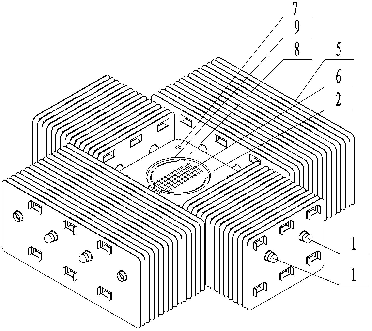
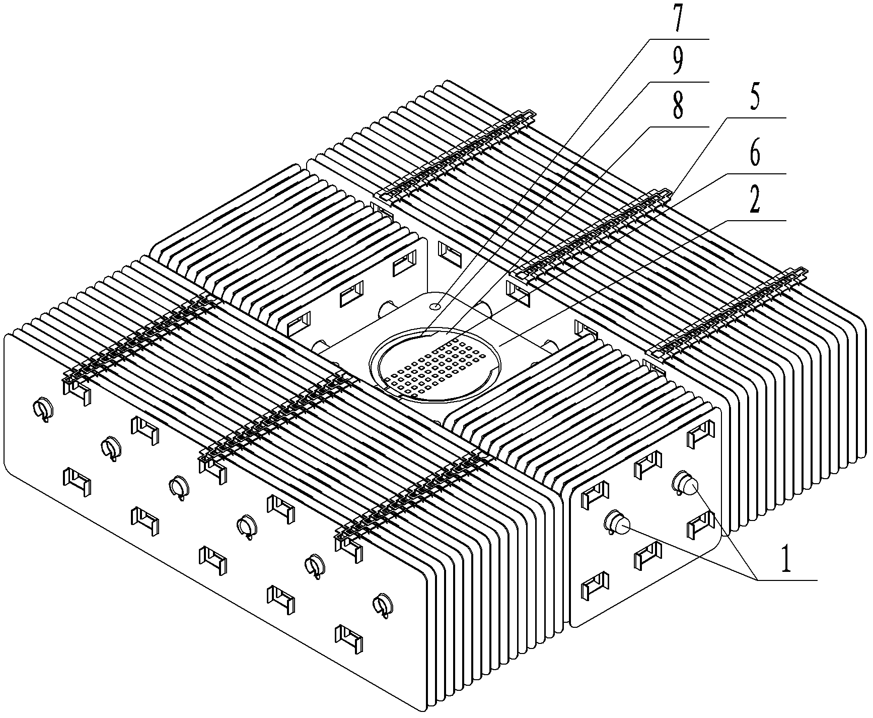
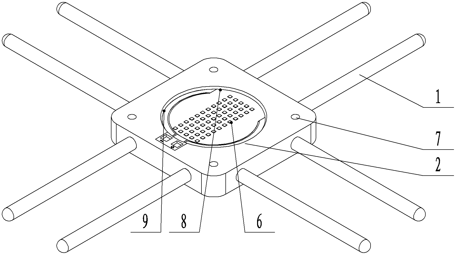
[0025] Such as figure 1 Shown in -5, the present invention comprises LED light source, the radiator that is connected with LED light source, and radiator comprises heat pipe 1, the substrate 2 that is connected with heat pipe 1, and the middle part of substrate 2 establishes airtight cavity 3, and heat pipe 1 and cavity 3 The upper end surface of the substrate 2 is provided with an LED light source, the contact surface between the substrate 2 and the LED light source is a plane, and the LED chip 6 is directly packaged on the upper end surface of the substrate 2 to form an integrated LED light source with the radiator. The middle part of the upper end surface of the substrate 2 is the LED light source bearing surface; the middle part of the upper end surface of the substrate 2 is the LED light source bearing surface; PCB board, the c...


PUM


Abstract

The invention relates to an LED (light emitting diode) lamp, in particular to a heat-pipe type LED lamp. In the prior art, a large-power LED lamp is usually cooled by using a heat pipe, the LED chip can not be directly attached to a radiator, and a base for supporting the LED chip is required between the heat pipe and the LED chip so as to influence heat dissipation of the LED due to the thermal resistance of the base. The heat-pipe type LED lamp is characterized in that the radiator includes a heat pipe, and a substrate connected with the heat pipe, wherein a closed cavity is formed in the middle of the substrate; the heat pipe is communicated with the cavity; an LED light source is arranged on the upper end face of the substrate; the contact surface between the substrate and the LED light source is a plane surface; and a LED chip is directly packaged on the upper end face of the substrate to form the LED light source integrated with the radiator. The substrate keeps plane contact with the LED light source so as to ensure the integrity of the contact, thereby improving welding quality. Additionally, the heat generated by the LED chip can be dissipated by the radiator, thereby reducing thermal resistance coefficient, realizing quick thermal conduction, and improving luminous efficiency and prolonging service life of LED.

Description

technical field [0001] The invention relates to an LED lamp. Background technique [0002] LED lamps have the advantages of energy saving, high efficiency, and long life. Today, with increasing attention to energy conservation, the application fields of high-power LED lamps continue to expand. The products have involved landscape lighting, miner's lamps, street lamps and emergency lamps. [0003] Because LED lamps will generate a lot of heat when they are working, the problem of heat dissipation has become a bottleneck in the development and promotion of LED lamps. High-power LED lamps often use heat pipes to dissipate heat. Since the cross-section of the heat pipe is circular, it contacts the LED light source with an arc surface. The contact surface is small and there are many contact gaps. The welding surface with the LED light source is a circular arc surface, which is prone to false welding, and the quality cannot be guaranteed; the LED chip cannot be directly attached ...

Claims


Application Information

Patent Timeline
Patent Type & Authority Applications(China)
IPC IPC(8): F21S2/00F21V29/00F21V19/00F21V23/06F21V17/12F21Y101/02F21K9/00F21V29/51F21V29/76F21Y115/10
Inventor 李浩王怀金王建余丽珍黄新法朱立新
Owner 杭州临安新联电器工业有限公司
Learn More