
Small-diameter rod material cut-off device

A cutting device and small-diameter technology, which is applied in the mechanical field, can solve the problems that the length of the cut part cannot be adjusted in a large range, the semicircular upper and lower knife edges are difficult to ensure alignment, and the broken product is squeezed, etc., to achieve the quality of the cut surface and stable, Easy and fast adjustment, reliable output

Active Publication Date: 2012-07-18
贵州振华群英电器有限公司(国营第八九一厂)
View PDF5 Cites 0 Cited by
  • Summary
  • Abstract
  • Description
  • Claims
  • Application Information

AI Technical Summary

Problems solved by technology

[0002] The traditional small-diameter bar is cut by hand. The bar is measured first, the cutting position is marked, and then the bar is cut with a cutting machine. In order to ensure the smoothness of the cut surface, the cut bar needs to be cut. Finishing such as flat grinding, this processing method has low production efficiency and rough cut surface
With the development of mechanical processing technology, the traditional manual cutting technology has gradually been eliminated, and various bar cutting machines have appeared. There are two commonly used bar cutting tools, one is the pop-up unloading structure, and the disadvantage is that It is impossible to cut the bar with a diameter of less than 2mm, because the pop-up structure is very easy to break after the diameter is less than 2mm; the other is the semicircular knife edge cutting tool, which can cut small diameter bars, but the disadvantage is the semicircular upper and lower knife edge It is very difficult to ensure alignment, and it is easy to cause broken parts to be crushed, resulting in a high scrap rate; the common disadvantages of the above two structures are that the length of cut parts cannot be adjusted in a wide range, and the manufacturing is complicated and difficult to maintain

Method used


Image

  • Small-diameter rod material cut-off device
  • Small-diameter rod material cut-off device
  • Small-diameter rod material cut-off device

Examples


Embodiment 1

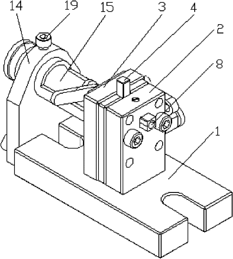
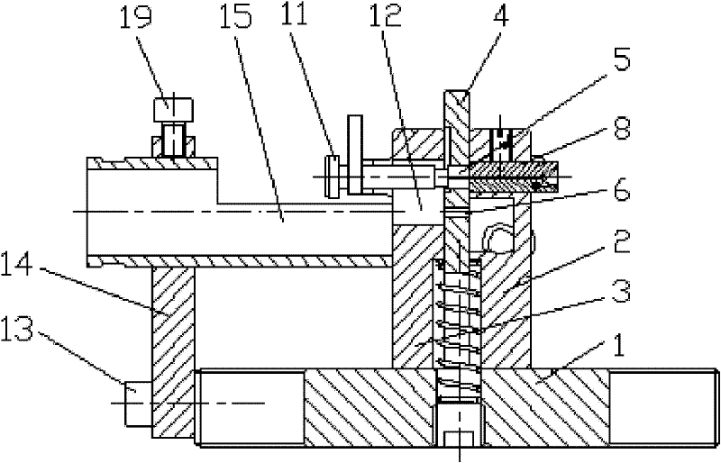
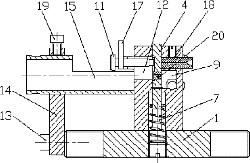
[0018] Example 1. Such as figure 1 , 4 As shown, including base 1, front support 2 and rear support 3, front support 2 and rear support 3 are fixed on the base 1, between front support 2 and rear support 3, cutting knife 4, cutting hole are housed from top to bottom 5. The exhaust hole 6 and the return spring 7, the return spring 7 plays the role of resetting the cutting knife 4; the front bracket 2 is provided with a feeding hole 8, before work, the feeding hole 8 communicates with the cutting hole 5, and the bar material 18 can enter the cutting hole 5 through the feeding hole 8; there is a space 9 below the feeding hole 8, and the front bracket 2 is equipped with an air nozzle 10, which communicates with the space 9, and the air nozzle 10 can cut off the bar. 20 Blow out the cut-off hole 5; the rear support 3 is equipped with an adjustment stop nail 11 and an adjustment piece 21, the adjustment stop nail 11 is equipped with a lock nut 17, and the adjustment piece 21 is eq...


PUM

PropertyMeasurementUnit
diameteraaaaaaaaaa

Abstract

The invention discloses a small-diameter rod material cut-off device. A front bracket (2) and a back bracket (3) are fixed on a pedestal (1). A cut-off knife (4), a cut-off hole (5), a vent hole (6) and a reset spring (7) are arranged from top down between the front bracket (2) and the back bracket (3). A feed hole (8) is arranged on the front bracket (2). A space (9) is disposed under the feed hole (8). A gas nozzle (10) is mounted on the front bracket (2). A regulation blocking screw (11) and a regulation member (21) are mounted on the back bracket (3). A channel (12) is disposed below the regulation blocking screw (11) in the back bracket (3). The other end of the pedestal (1) is fixed with a bracket for a material receiving pipe (14) through a screw (13). The material receiving pipe (15) is fixed on the bracket for a material receiving pipe (14) through a fastening screw (19). The device disclosed by the invention has the characteristics of simple structure, convenient manufacture and convenient maintenance, can cut off metal or nonmetal rod materials with a diameter of 0.1-5mm without damage to the diameter section of rod material due to pressing, and can rapidly regulate the cut-off length to avoid jamming. The cut-off section has high and stable quality.

Description

technical field [0001] The invention relates to a bar material cutting device, in particular to a small-diameter bar material cutting device, which belongs to the technical field of machinery. Background technique [0002] The traditional small-diameter bar is cut by hand. The bar is measured first, the cutting position is marked, and then the bar is cut with a cutting machine. In order to ensure the smoothness of the cut surface, the cut bar needs to be cut. Finishing such as flat grinding, this processing method has low production efficiency and rough cut surface. With the development of mechanical processing technology, the traditional manual cutting technology has gradually been eliminated, and various bar cutting machines have appeared. There are two commonly used bar cutting tools, one is the pop-up unloading structure, and the disadvantage is that It is impossible to cut the bar with a diameter of less than 2mm, because the pop-up structure is very easy to break afte...

Claims


Application Information

Patent Timeline
Patent Type & Authority Applications(China)
IPC IPC(8): B21F11/00
Inventor 胡胤敏莫连敏尹毅余正强张红林
Owner 贵州振华群英电器有限公司(国营第八九一厂)
Learn More