Mixed butyraldehyde separation device and application of packed towers

A technology of separation device and packed tower, which is applied in the separation/purification of carbonyl compounds, distillation separation, separation methods, etc., to achieve the effects of high separation efficiency, reduced energy consumption, and low space occupation in the tower

Inactive Publication Date: 2012-07-18
TIANJIN UNIV
View PDF4 Cites 8 Cited by
  • Summary
  • Abstract
  • Description
  • Claims
  • Application Information

AI Technical Summary

Problems solved by technology

These technologies have not yet been applied to the mixed butyraldehyde recovery process. After research and experiments, we believe that if the packed tower technology is applied to the mixed butyraldehyde separation, the original process can be greatly improved, mainly in terms of energy saving and separation. High efficiency, low tower pressure, large operating flexibility, etc.

Method used


Image

  • Mixed butyraldehyde separation device and application of packed towers
  • Mixed butyraldehyde separation device and application of packed towers
  • Mixed butyraldehyde separation device and application of packed towers

Examples


Embodiment 1

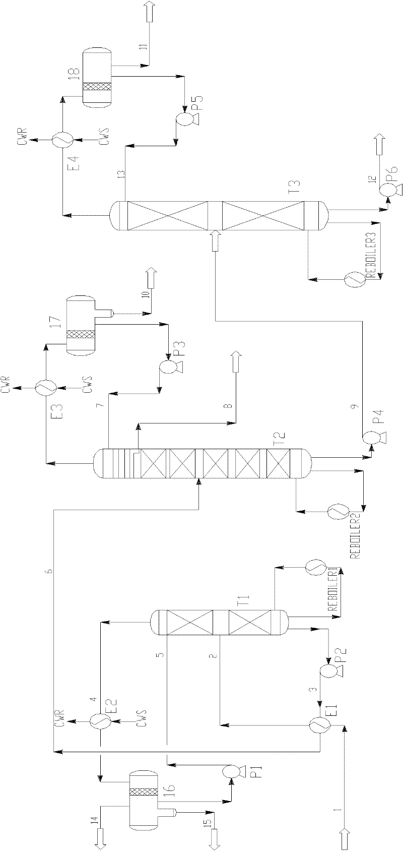
[0030] The mixed butyraldehyde separation device is composed of a stabilizing tower T1, an isomer tower T2, and a n-butyraldehyde tower T3. Wherein the mixed butyraldehyde 1 that reaction generates enters the middle part of stabilizing tower T1 through the pipeline, and the mixed butyraldehyde liquid 3 is produced at the bottom of the tower, and the tower top material 4 enters the tower top condenser E2 through the pipeline, and the air phase 13 enters the fuel gas main pipe, and the liquid phase 5 Return to the top of the stable tower T1 through the reflux pump P1. The mixed butyraldehyde liquid 3 is preheated by the heat exchanger E1 and fed into the stabilization tower T1, and then enters the middle part of the isomer tower T2 through the pipeline. P4 enters the middle part of the n-butyraldehyde tower T3, and after the gas phase at the top of the tower is condensed by the condenser E4, a part of the liquid phase is pumped to the top of the T3 tower through the reflux pump ...

Embodiment 2

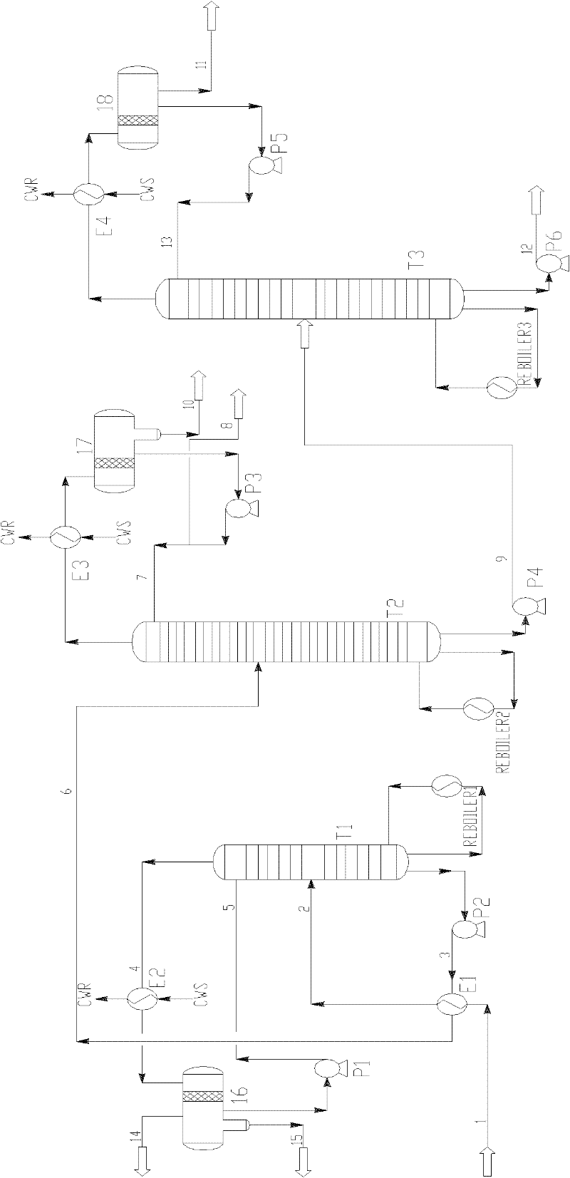
[0034] The mixed butyraldehyde separation device is composed of a stabilizing tower T1, an isomer tower T2, and a n-butyraldehyde tower T3. Wherein the mixed butyraldehyde 1 that reaction generates enters the middle part of stabilizing tower T1 through the pipeline, and the mixed butyraldehyde liquid 3 is produced at the bottom of the tower, and the tower top material 4 enters the tower top condenser E2 through the pipeline, and the air phase 13 enters the fuel gas main pipe, and the liquid phase 5 Return to the top of the stable tower T1 through the reflux pump P1. The mixed butyraldehyde liquid 3 is preheated by the heat exchanger E1 and fed into the stabilization tower T1, and then enters the middle part of the isomer tower T2 through the pipeline. P4 enters the middle part of the n-butyraldehyde tower T3, and after the gas phase at the top of the tower is condensed by the condenser E4, a part of the liquid phase is pumped to the top of the T3 tower through the reflux pump ...


PUM


Abstract

The invention provides a mixed butyraldehyde separation device and the application of packed towers. The packed towers are used as a stabilization tower and an n-butanal tower; a tower tray and packing mixed way is adopted by an isomer tower, the five layers of tower trays are arranged on the top of the isomer tower, and the packing way is adopted at the other parts of the isomer tower; the packing is metal plate corrugated regular packing with the specific surface area of 250-500m<2> / m<3>; the tower trays are float valve tower trays, and each float valve has a form of F1 circular float valve or trapezoid guide float valve; and grid plate type packing pressing rings and grid plate type packing supports are used for limiting and supporting the packing in all packing sections. According to the invention, the energy consumption is greatly reduced, the tower height is effectively reduced and the metal material consumption is saved; and the packing is the metal plate corrugated regular packing, thus having the characteristics of high flux, low pressure reduction and high separation efficiency.

Description

technical field [0001] The invention relates to a method and device for separating mixed butyraldehyde, in particular to a rectification separation process and device using structured packing, distributors and trays. Background technique [0002] In the production of butanol and octanol, propylene and synthesis gas are used as raw materials, and the reaction mixture of crude butyraldehyde produced by low-pressure carbonylation contains isobutyraldehyde, n-butyraldehyde, water, n-butanol and a very small amount of propylene, propane, carbon dioxide, For hydrogen and methane, the refining of isobutyraldehyde and n-butyraldehyde involves a stabilization tower, butyraldehyde isomer tower, and n-butyraldehyde tower, especially the difference in boiling point between isobutyraldehyde and n-butyraldehyde is very small, so the separation and recovery process requires The number of theoretical boards is very high, and the energy consumption is also high. [0003] At present, the vas...

Claims


Application Information

Patent Timeline
IPC IPC(8): B01D3/14C07C47/02C07C45/82
CPCB01D3/143
Inventor 李楠楠姜斌李鑫钢张志恒肖红
Owner TIANJIN UNIV
Why Eureka
Try Eureka