
Permanent magnet and manufacturing method for permanent magnet

A technology for permanent magnets and manufacturing methods, applied in the direction of inductance/transformer/magnet manufacturing, magnetic objects, magnetic materials, etc., can solve the problems of magnetic particle reverse magnetization coercive force, decrease, etc., to prevent the decrease of coercive force and improve the magnetic properties The effect of suppressing the decrease of residual magnetic flux density

Inactive Publication Date: 2012-07-11
NITTO DENKO CORP
View PDF7 Cites 0 Cited by
  • Summary
  • Abstract
  • Description
  • Claims
  • Application Information

AI Technical Summary

Problems solved by technology

As a result, when a magnetic field is applied from the outside, there is a problem that the magnetization of each magnet particle is easily reversed and the coercive force decreases.

Method used


Image

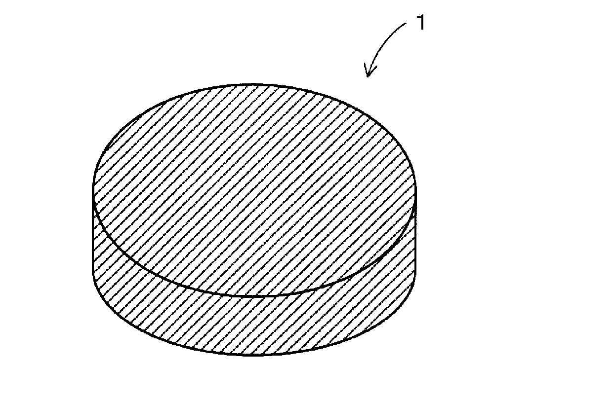
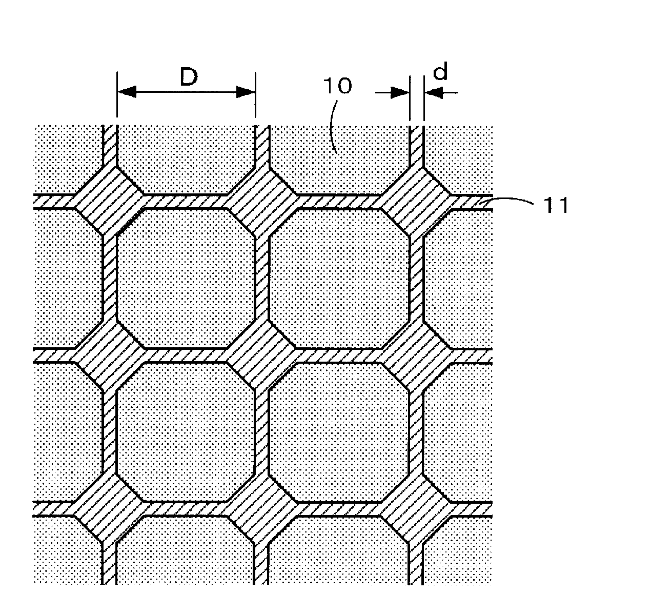
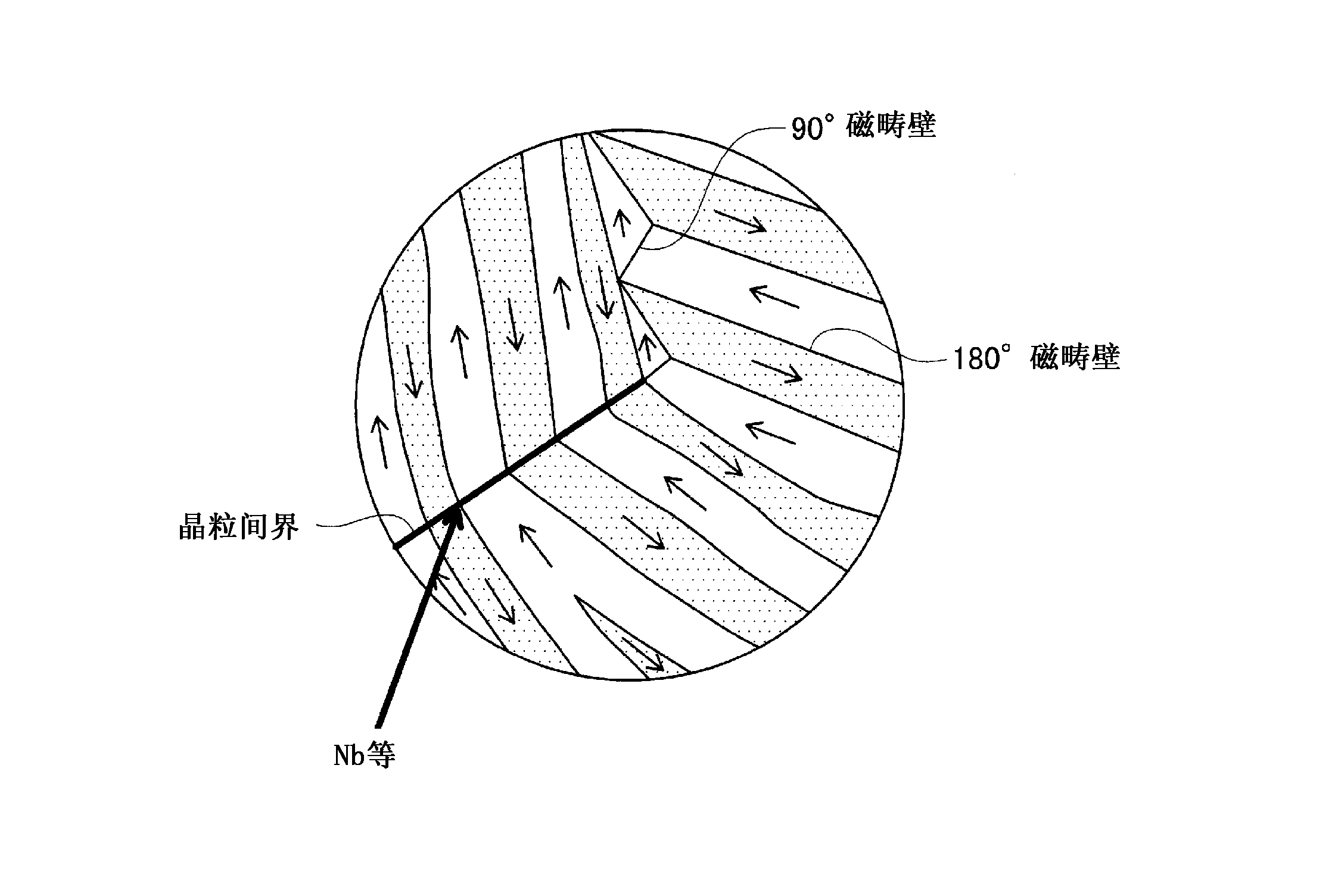
  • Permanent magnet and manufacturing method for permanent magnet
  • Permanent magnet and manufacturing method for permanent magnet
  • Permanent magnet and manufacturing method for permanent magnet

Examples


Embodiment 1

[0095] The alloy composition of the neodymium magnet powder of Example 1 has a higher Nd ratio than the fraction based on the stoichiometric composition (Nd: 26.7 wt%, Fe (electrolytic iron): 72.3 wt%, B: 1.0 wt%), for example In terms of weight %, Nd / Fe / B=32.7 / 65.96 / 1.34 is set. In addition, 5% by weight of niobium n-propoxide was added as an organometallic compound to the neodymium magnet powder obtained by pulverization. In addition, the calcination treatment was performed by maintaining the molded body of the magnet powder at 600° C. for 5 hours in a hydrogen atmosphere. In addition, the supply amount of hydrogen during calcination was set to 5 L / min. In addition, the sintering of the formed calcined body is performed by SPS sintering. In addition, other processes are the same processes as the above-mentioned [Production Method 1 of Permanent Magnet].

Embodiment 2

[0097] The added organometallic compound is set to n-butoxide niobium. Other conditions are the same as in Example 1.

Embodiment 3

[0099] The sintering of the formed calcined body is performed by vacuum sintering instead of SPS sintering. The other conditions are the same as in Example 1.


PUM


Abstract

There are provided a permanent magnet and a manufacturing method thereof capable of densely sintering the entirety of the magnet without making a gap between a main phase and a grain boundary phase in the sintered magnet. To fine powder of milled neodymium magnet is added an organometallic compound solution containing an organometallic compound expressed with a structural formula of M- (OR)x (M represents V, Mo, Zr, Ta, Ti, W or Nb, R represents a substituent group consisting of a straight-chain or branched-chain hydrocarbon, x represents an arbitrary integer) so as to uniformly adhere the organometallic compound to particle surfaces of the neodymium magnet powder. Thereafter, a compact body formed through powder compaction is held for several hours in hydrogen atmosphere at 200 through 900 degrees Celsius. Thereafter, through sintering process, a permanent magnet is manufactured.

Description

Technical field [0001] The present invention relates to a permanent magnet and a manufacturing method of the permanent magnet. Background technique [0002] In recent years, permanent magnet motors used in hybrid vehicles, hard disk drives, and the like have been required to be smaller and lighter in weight, higher output, and higher efficiency. In addition, in the permanent magnet motor described above, in order to achieve a reduction in size, weight, high output, and efficiency, it is required to further improve the magnetic characteristics of the permanent magnets embedded in the permanent magnet motor. In addition, as permanent magnets, there are ferrite magnets, Sm-Co-based magnets, Nd-Fe-B-based magnets, Sm 2 Fe 17 N x Base magnets and the like, especially Nd-Fe-B base magnets with high residual magnetic flux density are used as permanent magnets for permanent magnet motors. [0003] Here, as a method of manufacturing permanent magnets, a powder sintering method is generally...

Claims


Application Information

Patent Timeline
Patent Type & Authority Applications(China)
IPC IPC(8): H01F41/02B22F1/02B22F3/00C22C33/02C22C38/00H01F1/053H01F1/08B22F1/16
CPCB22F3/02B82Y30/00H01F41/0266B22F1/02B22F1/0018H01F1/0577B22F2998/10B22F3/10H01F1/0572B22F2999/00C22C33/0278B22F9/023B22F1/16B22F1/056B22F9/04B22F3/101B22F2201/01H01F1/08
Inventor 尾关出光久米克也平野敬祐大牟礼智弘太白启介尾崎孝志
Owner NITTO DENKO CORP
Learn More