
Multifocal light beam generation apparatus and multifocal confocal scan microscope

A technology that produces devices and multi-focus, applied in the field of optics, to achieve high uniformity, high resolution, and small size

Active Publication Date: 2012-07-11
SHENZHEN KECHUANG DIGITAL DISPLAY TECH
View PDF3 Cites 13 Cited by
  • Summary
  • Abstract
  • Description
  • Claims
  • Application Information

AI Technical Summary

Problems solved by technology

[0005] However, none of the existing multi-focus microscopy techniques can satisfy the above three conditions at the same time.

Method used


Image

  • Multifocal light beam generation apparatus and multifocal confocal scan microscope
  • Multifocal light beam generation apparatus and multifocal confocal scan microscope
  • Multifocal light beam generation apparatus and multifocal confocal scan microscope

Examples


Embodiment 1

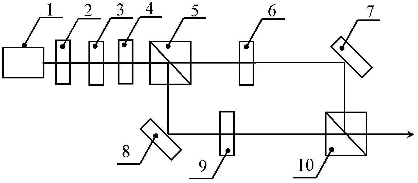
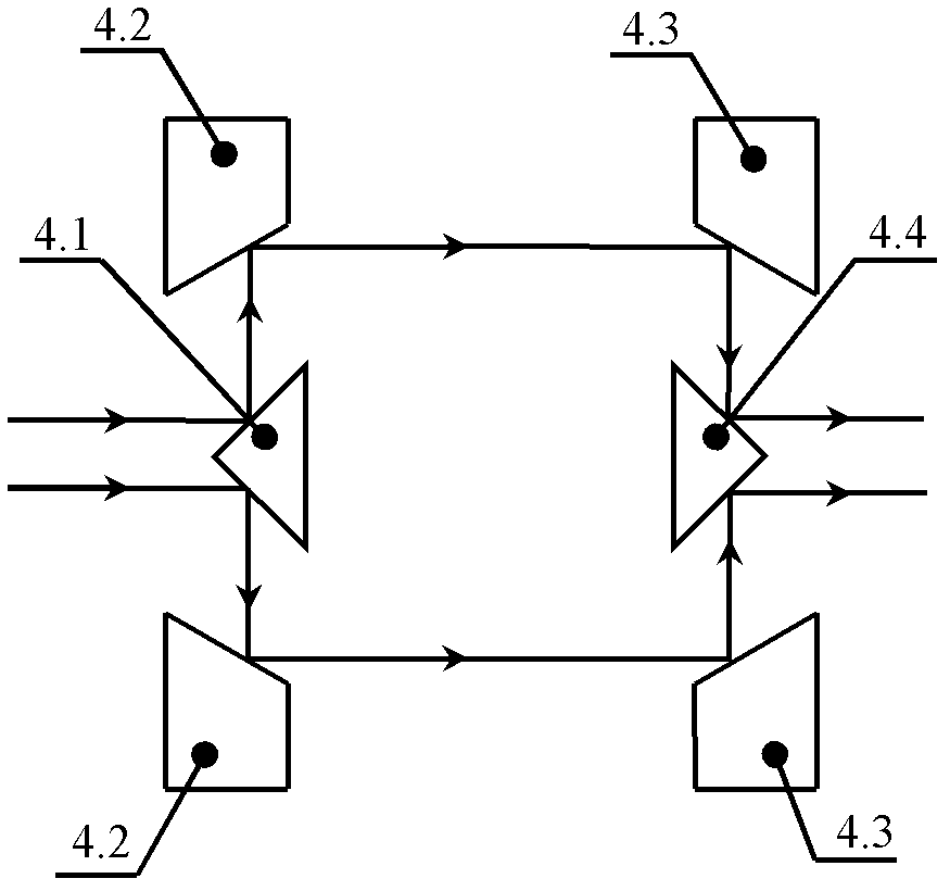
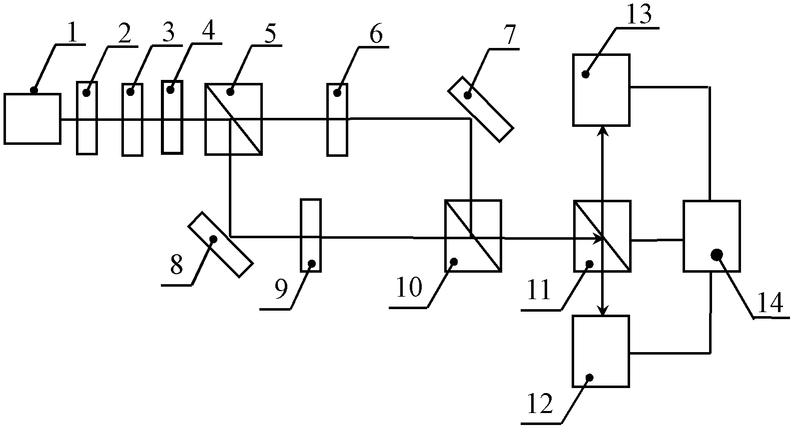
[0030] figure 1 It is a schematic diagram of a multi-focus beam generating device according to an embodiment of the present invention. A collimating beam expander 2, a polarizing plate 3 and a first polarizing beam splitter 5 are sequentially arranged in the light source 1 beam exit direction, and the beam is collimated after exiting from the laser 1. After the beam expander 2 collimates and expands the beam, it enters the polarizer 3, and the incident beam becomes linearly polarized light after being modulated by the polarizer 3, and the linearly polarized light enters the first polarization beam splitter 5, and the beam passes through the first polarization beam splitter After the mirror 5, it is divided into a reflected beam and a transmitted beam. The reflected beam and the transmitted beam are two beams of orthogonal linearly polarized light. A first filter 6 and a first plane mirror 7 are sequentially arranged on the transmitted light path. The transmitted beam is filtere...


PUM


Abstract

The invention discloses a multifocal light beam generation apparatus and a multifocal confocal scan microscope. The multifocal light beam generation apparatus comprises a light source, a polarizer and a polarization filtering optical path. The polarization filtering optical path is provided with a first polarizing beam splitting mirror at an optical path after light source emission light beams pass through the polarizer, and after the light beams pass through the first polarizing beam splitting mirror, a part of the beams is reflected, and a part of the beams is transmitted; on a reflection optical path, a first reflecting mirror, a first filter plate and a second polarizing beam splitting mirror are arranged in order; on a transmission optical path, a second filter plate, a second reflecting mirror and the second polarizing beam splitting mirror are arranged in order, and a reflection light beam and a transmission light beam are joined at the second polarizing beam splitting mirror to form a light beam. After focusing of the light beams which are generated through the multifocal light beam generation apparatus, an obtained focus has the characteristics of high uniformity, small dimension and circular symmetry distribution of a shape. According to the scan microscope, a fast imaging speed under the premise of a high resolution can be ensured, or a higher resolution is provided with the same imaging speed.

Description

technical field [0001] The invention belongs to the field of optical technology, and relates to a beam generating device, in particular to a multi-focus beam generating device; at the same time, the invention also relates to a multi-focus confocal scanning microscope comprising the above-mentioned multi-focus beam generating device. Background technique [0002] Confocal microscopy technology is an existing technology that provides high-resolution images of one or more layers of an object. The beam emitted by a point source is focused to the surface of the object by the objective lens, and the beam is reflected or transmitted by the object and then focused to the pinhole by the focusing lens. into the photodetector. [0003] In order to improve the imaging speed of laser scanning confocal microscopy, multi-focus beams are usually used to form multiple focal points with diffraction-limited quality and capable of dispersing the focus to simultaneously excite the sample. The m...

Claims


Application Information

Patent Timeline
IPC IPC(8): G02B27/28G02B21/00G02B21/36
Inventor 郭汉明翁晓羽田毅强姜曼蒋庭佳瑚琦隋国荣庄松林
Owner SHENZHEN KECHUANG DIGITAL DISPLAY TECH
Learn More