
Additive for electrolytic copper foil and surface treatment process of very low profile electrolytic copper foil

A surface treatment, electrolytic copper foil technology, applied in secondary treatment of printed circuits, improvement of metal adhesion of insulating substrates, etc. effect of ability

Active Publication Date: 2014-06-11
惠州联合铜箔电子材料有限公司
View PDF11 Cites 0 Cited by
  • Summary
  • Abstract
  • Description
  • Claims
  • Application Information

AI Technical Summary

Problems solved by technology

The reason why titanium ions and tungsten ions are used together is that when they are added separately, they have the following disadvantages, that is, when titanium ions are added alone, although the copper precipitated protrusions are miniaturized and the roughness of the rough surface is uniform, it is easy to appear on the substrate surface after etching. Residual copper makes the etching accuracy worse; in addition, when tungsten ions are added alone, although it can inhibit the generation of nuclei and is effective in controlling the formation of dendrites, the adhesion force is reduced

Method used


Image

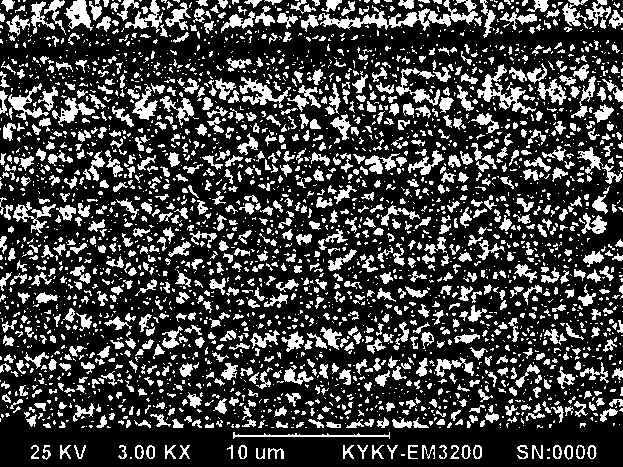
  • Additive for electrolytic copper foil and surface treatment process of very low profile electrolytic copper foil
  • Additive for electrolytic copper foil and surface treatment process of very low profile electrolytic copper foil
  • Additive for electrolytic copper foil and surface treatment process of very low profile electrolytic copper foil

Examples


Embodiment and 6

[0043] Following 5 embodiments and 6 comparative cases adopt following common test conditions:

[0044] (1) Specification of copper foil: 18 micron very low profile copper foil.

[0045] (2) The linear speed of the surface treatment machine: 15m / min.

[0046] (3) The electroplating current of each electrolytic tank (except the microcrystalline roughening tank): 1400A for the curing tank; 560A for the barrier layer plating tank; 140A for the anti-oxidation layer plating tank.

Embodiment 1

[0048] A surface treatment process of very low-profile electrolytic copper foil is carried out according to the following steps, and the process flow chart can be found in figure 1 , the schematic diagram of the surface treatment machine see figure 2 :

[0049] 1. Install the rolled original foil on the unwinding device of the surface treatment machine, and the copper foil is passed through each guide roller, cathode roller, and rubber roller by the traction device until it reaches the winding device, and then the copper foil is rolled on the On the winding roller, start the surface treatment machine to keep the copper foil at a line speed of 15m / min. First, wash off the oxide layer on the surface of the copper foil with acid in the pickling tank.

[0050] 2. After pickling, the residual pickling solution on the surface of the copper foil is squeezed between the pressure water roller and the cathode roller to remove most of the residual pickling solution, and enters the was...


PUM

PropertyMeasurementUnit
surface roughnessaaaaaaaaaa

Abstract

The invention belongs to the technical field of electronic materials, particularly relates to a surface treatment process of a very low profile electrolytic copper foil, in particular to an additive used during the surface treatment of the very low profile electrolytic copper foil. The additive is composed of three components: titanous sulfate, titanium sulfate and molybdate, wherein the contents of the three components in the electroplate liquid are respectively 50-150mg / L, 150-250mg / L and 70-118mg / L (molybdate radical). The additive is used to be added into a microcrystalline coarsening slot; and the three components are used cooperatively, so that the treated copper foil coarse layer crystalline grains are small and dense, achieving a microcrystalline effect. In the invention, the addition amount of each additive and proper electroplating process conditions such as content of cuprate, temperature and current density are found out in the coarsening slot for the surface treatment, so that the treated 18-micron very-low profile electrolytic copper foil can meet the following technical indicators: the anti-stripping strength is equal to or greater than 1.0kg / cm and the value of surface roughness Rz is smaller than or equal to 5.1 microns.

Description

technical field [0001] The invention belongs to the technical field of electronic materials, and in particular relates to a process for surface treatment of electrolytic copper foil, in particular to an additive used in surface treatment of copper foil, and to the use of the additive to produce microcrystals of very low-profile electrolytic copper foil Rough production process. Background technique [0002] Electrolytic copper foil is an important material for the manufacture of copper clad laminates (CCL) and printed circuit boards (PCB). In the rapid development of today's electronic information industry, electrolytic copper foil is called the "neural network" of electronic product signal and power transmission and communication. [0003] With the development of PCB in the direction of multilayer, high density and thinning, copper foil is also developing in the direction of high quality and high performance such as ultra-thin, low profile, high peel strength and high duct...

Claims


Application Information

Patent Timeline
Patent Type & Authority Patents(China)
IPC IPC(8): C25D7/06C25D3/38H05K3/38
Inventor 周启伦郑惠军黄国平邓烨朱各桂万新领高元亨
Owner 惠州联合铜箔电子材料有限公司
Learn More