
Forging method for pressure vessel bottom head transition section of second-generation nuclear power station and mould

A pressure vessel and transition section technology, which is applied to manufacturing tools, metal processing equipment, forging/pressing/hammer devices, etc., can solve the problems of increasing machining allowance, increasing product production cycle, and large forging allowance, etc. Achieve the effect of reducing the difficulty of machining, reducing the difficulty and cost of machining and manufacturing, and reducing the amount of metal cutting

Inactive Publication Date: 2012-07-11
SHANGHAI HEAVY MACHINERY PLANT
View PDF5 Cites 12 Cited by
  • Summary
  • Abstract
  • Description
  • Claims
  • Application Information

AI Technical Summary

Problems solved by technology

Due to its complex shape (including straight section + tapered section), the forging of the transition section of the lower head of the pressure vessel of the nuclear power plant cannot be produced with a forging close to such a shape by the traditional forging method. The allowance is very large, and the weight of the steel ingot is also very large. At the same time, the allowance for machining is increased, and the production cycle of the product is increased.

Method used


Image

  • Forging method for pressure vessel bottom head transition section of second-generation nuclear power station and mould
  • Forging method for pressure vessel bottom head transition section of second-generation nuclear power station and mould
  • Forging method for pressure vessel bottom head transition section of second-generation nuclear power station and mould

Examples


Embodiment Construction

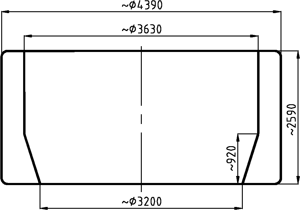
[0040] Such as Figure 9 As shown, the forging method of the lower head transition section of the second generation plus nuclear power plant pressure vessel of the present invention is used to forge the lower head transition section of the second generation plus nuclear power plant pressure vessel. The structure of the lower head transition section of the pressure vessel is as follows figure 1 As shown, including the straight section and the tapered section, the inner diameter of the straight section is 3630mm, the outer diameter is 4390mm, the inner hole of the tapered section is a hypotenuse, the major diameter of the tapered section is 3630mm, the minor diameter is 3200mm, and the height is 920mm. The height is 2590mm; the present invention uses a 10,000-ton free forging press, using double vacuum steel ingots as raw materials, and the forging process is divided into the following steps:

[0041] The first step is to elongate once; heat the double-vacuum ingot to 1220±20°C ...


PUM

PropertyMeasurementUnit
The inside diameter ofaaaaaaaaaa
Outer diameteraaaaaaaaaa

Abstract

The invention discloses a forging method for a pressure vessel bottom head transition section of a second-generation nuclear power station. The forging method is used for forging the pressure vessel bottom head transition section of the second-generation nuclear power station, the pressure vessel bottom head transition section comprises a straight section and a conical section, the inner diameter of the straight section is not less than 3000mm, the outer diameter of the straight section is not less than 4000mm, an inner hole of the conical section is provided with a bevel edge, the minimum inner diameter of the conical section is smaller than the inner diameter of the straight section, and the overall height of the conical section is not less than 2500mm. A megaton free forging press is used, and double-vacuum steel ingots are used as raw materials. The forging method includes the steps: firstly, primarily drawing; secondly, cogging; thirdly, upsetting, forging a central hole and pre-broaching; fourthly, secondarily drawing; fifthly, flattening a large end of a forging to form a conical hole of the forging; and sixthly, broaching. The forging manufactured by the forging method can meet the technical requirements of the pressure vessel bottom head transition section of the nuclear power station, and is compact, reasonable in metal flow line distribution and not easy to crack. The invention further discloses a special mould sleeve for the forging method.

Description

technical field [0001] The invention relates to a forging method for nuclear power equipment, in particular to a forging method for the transition section of the lower head of a second-generation plus nuclear power plant pressure vessel. The invention also relates to a special die used in the forging method. Background technique [0002] In recent years, power shortage has become a bottleneck restricting the sustained and rapid economic development of various countries. As an important measure to save energy and adjust energy structure, nuclear power has been included in the national power development plan. The global nuclear power has entered a period of rapid development, in order to improve the energy structure, industrially developed countries and developing countries are actively committed to the development of nuclear power. [0003] At present, nuclear power technology is developing in the direction of large-scale, and the manufacture of key equipment in nuclear powe...

Claims


Application Information

Patent Timeline
IPC IPC(8): B21J5/06B21J13/02
Inventor 陈永波宋雷钧张灵芳乔志洲
Owner SHANGHAI HEAVY MACHINERY PLANT
Learn More