
Weak current amplifier with pA (picoamperes)-mu A(microamperes) range

A weak current, amplifier technology, used in improving amplifiers to reduce noise effects, improving amplifiers to reduce temperature/power supply voltage changes, improving basic electrical components, etc., can solve the problems of complex power supply, short electrometer tube life, and stable measurement It can achieve the effect of strong anti-interference ability, fast measurement speed and simple realization.

Inactive Publication Date: 2012-07-04
NANJING UNIV OF AERONAUTICS & ASTRONAUTICS
View PDF4 Cites 36 Cited by
  • Summary
  • Abstract
  • Description
  • Claims
  • Application Information

AI Technical Summary

Problems solved by technology

Usually the pre-stage circuit of the current amplifier is composed of a differential circuit composed of a junction field effect transistor or an insulated gate field effect transistor, but due to the high gate-source insulation resistance, the pinch-off voltage U of the field effect transistor GS And the maximum drain current is unstable, and the zero point is difficult to adjust, which makes the measurement stability poor [see reference: A design and discussion of a micro-current amplifier Guangxi Physics 1999]
In addition, electrometer tubes with high input impedance are used to measure microcurrents. However, electrometer tubes have the disadvantages of short life, large volume, complicated power supply, long warm-up time, and cumbersome calibration of zero point and full scale.

Method used


Image

  • Weak current amplifier with pA (picoamperes)-mu A(microamperes) range
  • Weak current amplifier with pA (picoamperes)-mu A(microamperes) range
  • Weak current amplifier with pA (picoamperes)-mu A(microamperes) range

Examples


Embodiment Construction

[0015] The structure and working principle of the present invention will be described in detail below with reference to the drawings and specific embodiments.

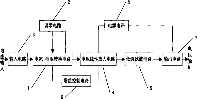
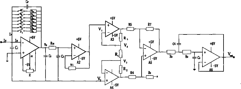
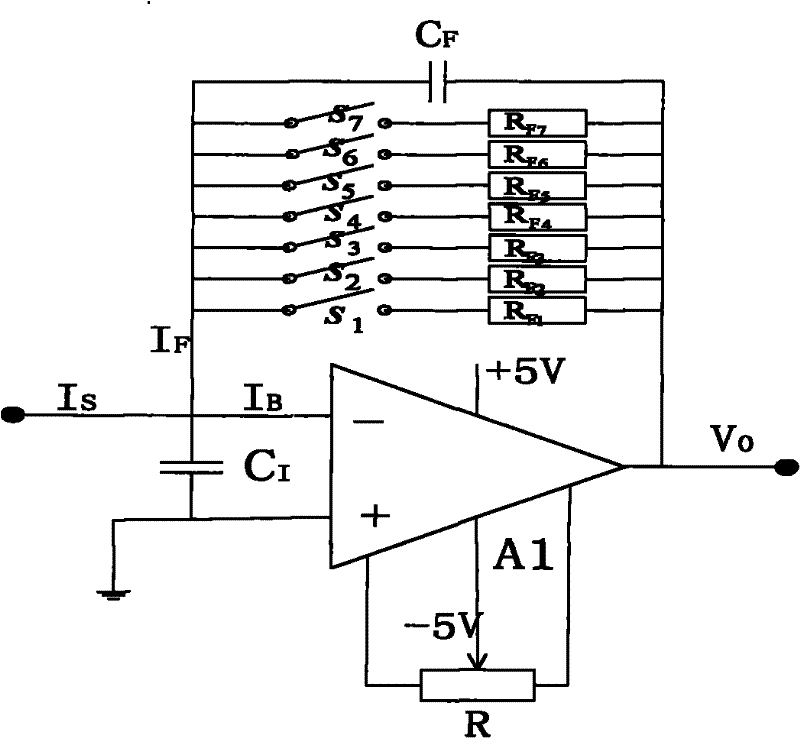
[0016] Such as figure 1 As shown, a pA-uA range micro-current amplifier provided by the present invention includes a current-voltage conversion circuit 1, a zeroing circuit 2, an input circuit 3, a voltage linear amplification circuit 4, a low-pass filter circuit 5, and a gain control circuit 6 , output circuit 7 and power supply circuit 8. The current-voltage conversion circuit 1 is composed of an electrometer operational amplifier, an electronic switch and feedback resistors of different resistance values, and its input terminal is connected to the input circuit. At the same time, the current-voltage conversion circuit 1 is also connected with a zeroing circuit 2 and a gain control circuit 6 , through the gain control 6 to select different feedback resistors, to realize the conversion of different measured currents ...


PUM


Abstract

The invention discloses a weak current amplifier with pA (picoamperes)-mu A (microamperes) range. The weak current amplifier comprises an input circuit, a current-voltage conversion circuit, a zeroing circuit, a voltage linear amplification circuit, a lowepass filtering circuit, a gain control circuit and a power circuit, wherein the current-voltage conversion circuit is used for realizing current-voltage conversion by adopting an electrometer operational amplifier with high input impedance; an input end of the current-voltage conversion circuit is connected with the input circuit, an output end of the current-voltage conversion circuit is connected with the voltage linear amplification circuit; the current-voltage conversion circuit is further connected with the zeroing circuit and the gain control circuit; and an output end of the voltage liner amplification circuit is connected with the lowpass filtering circuit for filtering out interference of high-frequency noise which is finally sent to an output circuit to be output. The technology can be used for solving the defects of the conventional weak current measurement process, such as complicated implementation, long preheating, difficulty in zeroing operation and large instrument volume. The weak current amplifier has the advantages of strong anti-interference capacity, high reliability and high measurement speed and can realize amplification of low-frequency weak current with a pA-muA range.

Description

technical field [0001] The invention relates to a current amplifier, in particular to a low-frequency weak current amplifier in the range of pA-μA. Background technique [0002] The measurement of weak current is widely used in aerospace, nuclear industry, life science and other fields. In the field of spaceflight, such as satellites, spaceships and other spacecraft space environment simulation tests, astronaut environmental adaptability tests and other tests in the measurement of vacuum, the spacecraft will escape electrons after being irradiated in space, and the accumulated charges on the surface will cause leakage Current, the study of spacecraft surface electrification, etc., all require the measurement of micro-current; in the field of nuclear industry, such as nuclear radiation detectors and radiation dose, it is necessary to measure the ionization current of the ionization chamber; it is widely used in life science and bioelectrochemistry Microcurrent analysis instr...

Claims


Application Information

Patent Timeline
IPC IPC(8): H03F1/28H03F1/30G01R1/20
Inventor 雷升杰魏志勇方美华陈国云张紫霞黄三玻
Owner NANJING UNIV OF AERONAUTICS & ASTRONAUTICS
Learn More