
Radial magnetic field motor with amorphous alloy

A technology of amorphous alloy and radial magnetic field, applied in the direction of static components of magnetic circuit, magnetic circuit shape/style/structure, magnetic circuit characterized by magnetic materials, etc., can solve the problem of long processing time and large-scale motor Amorphous alloy thin strip size limitation, many additional processes and other problems, to get rid of the restrictions, avoid the hidden dangers of recrystallization and additional stress, and reduce the effect of reprocessing processes

Active Publication Date: 2013-11-13
INST OF ELECTRICAL ENG CHINESE ACAD OF SCI
View PDF4 Cites 1 Cited by
  • Summary
  • Abstract
  • Description
  • Claims
  • Application Information

AI Technical Summary

Problems solved by technology

[0010] In order to overcome the problems in the prior art that the stator core of the radial magnetic field motor needs to cut the stator slot, which leads to long processing time, many additional processes, and the large-scale ability of the motor is limited by the size of the amorphous alloy thin strip, the present invention proposes a new diameter Magnetic Field Amorphous Alloy Motor

Method used


Image

  • Radial magnetic field motor with amorphous alloy
  • Radial magnetic field motor with amorphous alloy
  • Radial magnetic field motor with amorphous alloy

Examples


Embodiment Construction

[0027] The present invention will be further described below in conjunction with the accompanying drawings and specific embodiments.

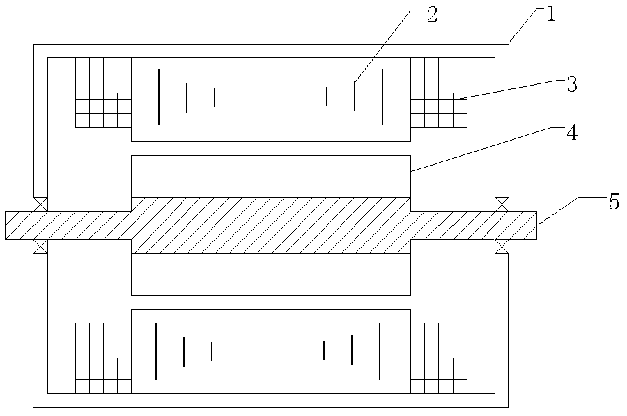
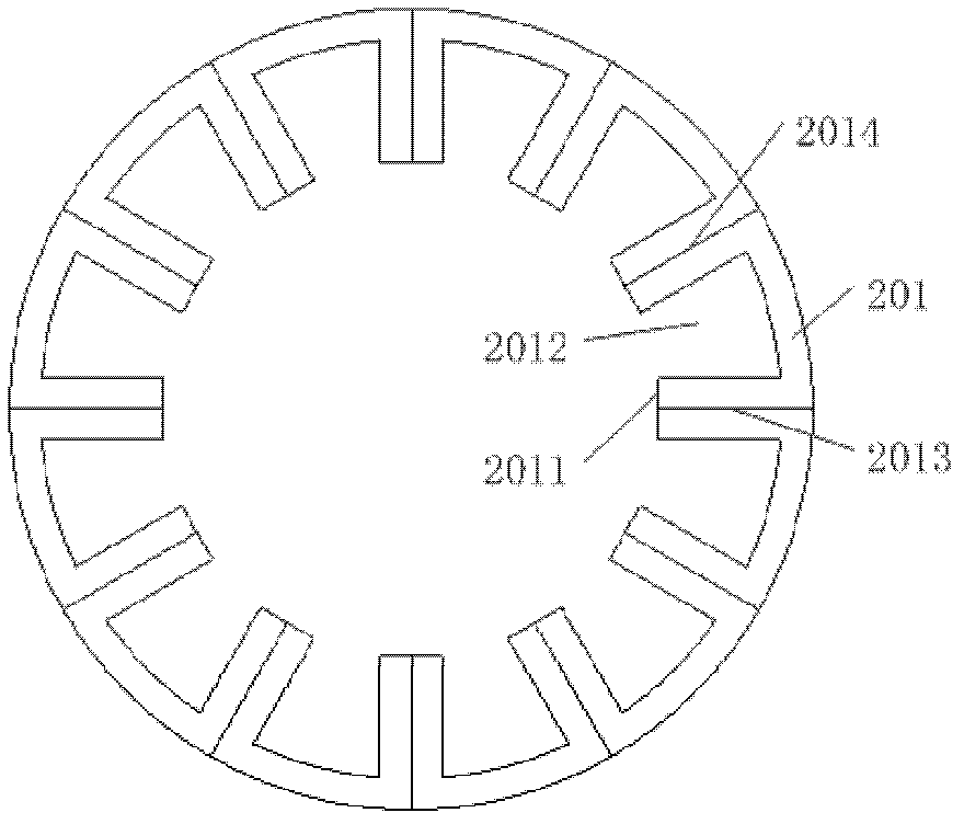
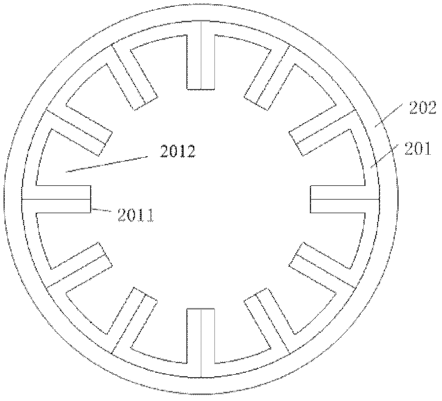
[0028] Such as figure 1 , figure 2 , Figure 3a , Figure 3bAs shown, the radial magnetic field amorphous alloy motor proposed by the present invention includes a casing 1 , a stator core 2 , an armature winding 3 , a rotor 4 and a rotor shaft 5 . The stator core 2 includes n×Q U-shaped amorphous alloy iron cores 201, and the n×Q U-shaped amorphous alloy iron cores 201 are divided into n groups of U-shaped amorphous alloy iron cores 201 stacked in the axial direction, each The group of Q U-shaped amorphous alloy iron cores 201 is arranged in a ring, n is an integer greater than or equal to 1, and Q is the number of stator slots.

[0029] Such as figure 2 , Figure 3a , Figure 3b As shown, the opening faces 2011 of each group of Q U-shaped amorphous alloy iron cores face inward, that is, the opening faces of the U-shaped amorphous allo...


PUM


Abstract

The invention discloses a radial magnetic field motor with an amorphous alloy. A stator iron core (2) of the radial magnetic field motor comprises n*Q U-shaped amorphous alloy iron cores (201) which are classified into n groups and stacked with one another axially; Q annularly arranged U-shaped amorphous alloy iron cores (201) are involved in each group; n is more than or equal to 1, and Q is the number of motor slots; each group of Q U-shaped amorphous alloy iron cores (201) are compactly attached in a transverse direction to form an annular stator iron core with a tooth slots; a motor stator slot consists of half-encircled regions (2012) of the U-shaped amorphous iron cores; an armature winding (3) passes through the stator slot; amorphous alloy thin strips are stacked to form an amorphous stacked block (211); and the amorphous stacked block (211) is bent to form each U-shaped amorphous alloy iron core (201). Stator tooth slots are not required to be cut in the motor stator iron core (2), so that the processing difficulty of the amorphous stator iron core is reduced, and a phenomenon that the magnetic performance of an amorphous alloy material is attenuated caused by processing is avoided. Furthermore, the size of the motor stator iron core is not limited by the width of an amorphous alloy strip material, so that a motor is easily enlarged.

Description

technical field [0001] The invention relates to a radial magnetic field motor with amorphous alloy material. Background technique [0002] Amorphous alloy is a new type of soft magnetic material born in the 1970s. roughly has the formula A 70-85 B 5-20 C 0-20 expressed components. Subscripts indicate the percentages of different elements, wherein A represents at least one of iron, nickel and cobalt; B represents at least one of boron, carbon and phosphorus; C represents at least one of silicon, aluminum and germanium. Compared with traditional silicon steel sheet materials, amorphous alloy has many advantages, and its core loss is extremely low, especially when the magnetic field alternating frequency is high, such as 0.5kHz ~ 20kHz, this low loss feature is more obvious. Therefore, amorphous alloys are very suitable for the manufacture of electric motors with high efficiency, high-speed operation and compact size requirements. The motor referred to is a broad concept,...

Claims


Application Information

Patent Timeline
Patent Type & Authority Patents(China)
IPC IPC(8): H02K1/14H02K1/16H02K1/02
Inventor 李琦范涛温旭辉
Owner INST OF ELECTRICAL ENG CHINESE ACAD OF SCI
Learn More