
Tool clamp and method for clamping aero-engine turbine fine cast blade

A technology of tooling fixtures and pressing devices, which is applied in the direction of manufacturing tools, metal processing machinery parts, clamping, etc., and can solve the problems of large datum conversion errors and low machining accuracy

Inactive Publication Date: 2019-08-16
AECC AERO SCI & TECH CO LTD
View PDF10 Cites 19 Cited by
  • Summary
  • Abstract
  • Description
  • Claims
  • Application Information

AI Technical Summary

Problems solved by technology

[0009] The invention provides a tooling fixture and a method for clamping precision-cast blades of an aero-engine turbine, which are used to solve the technical problems of low machining accuracy and large reference conversion errors in the traditional clamping process of pouring low-melting point alloy square boxes in the prior art

Method used


Image

  • Tool clamp and method for clamping aero-engine turbine fine cast blade
  • Tool clamp and method for clamping aero-engine turbine fine cast blade
  • Tool clamp and method for clamping aero-engine turbine fine cast blade

Examples


Embodiment 1

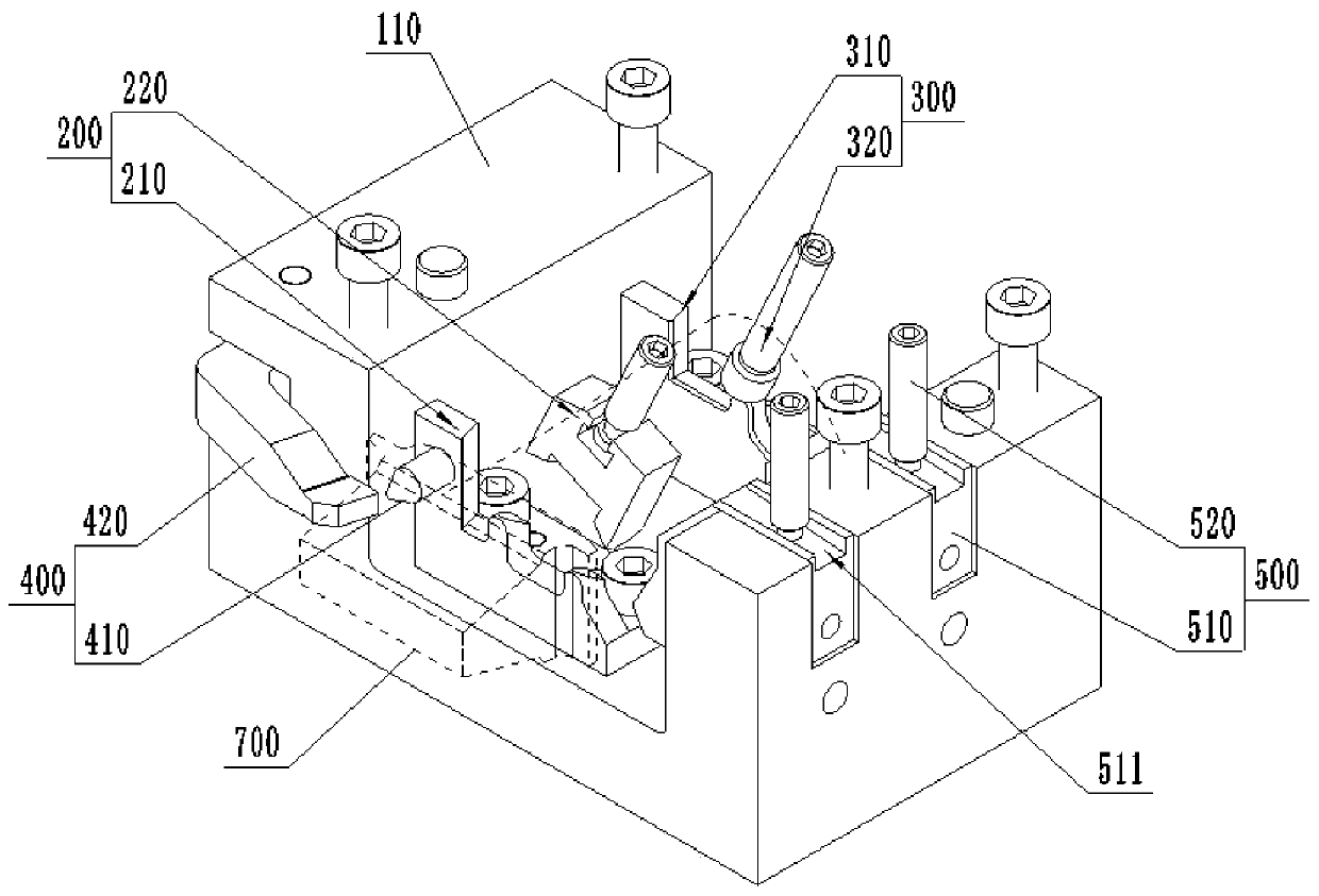
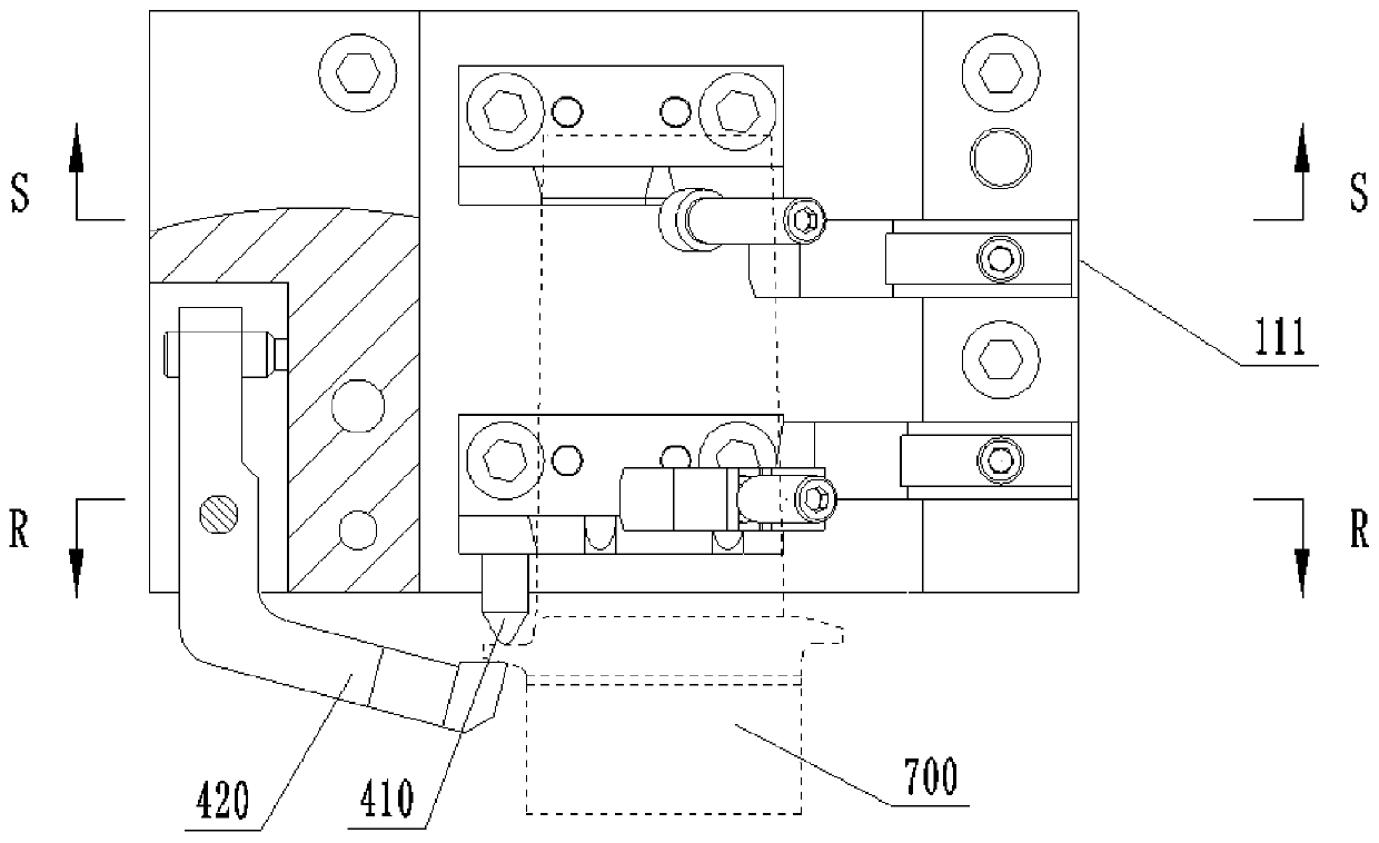
[0053] In this embodiment, a fixture, such as figure 1 and figure 2 As shown, it includes a square box 100, an airfoil root positioning assembly 200, an airfoil tail positioning assembly 300, and an edge plate shoulder positioning assembly 400. Specifically, the above square box 100 includes a base 110 and a top plate 120, and the above base 110 is a cross-sectional shape The above-mentioned top plate 120 is covered on the above-mentioned base 110 and can be connected by bolts or screws, so that the above-mentioned top plate 120 can be detachably installed, the above-mentioned airfoil root positioning assembly 200, and the above-mentioned airfoil tail positioning Both the assembly 300 and the above-mentioned edge plate shoulder positioning assembly 400 are fixedly installed in the above-mentioned square box 100 .

[0054] With this structure, the airfoil root 731, the airfoil tail 732 and the Edge plate shoulder 720, thereby fixing the blade 700 in the above-mentioned squar...

Embodiment 2

[0057] This embodiment is further optimized on the basis of Embodiment 1. In this embodiment, as figure 2 As shown, the blade airfoil root positioning assembly 200 includes a root section positioning block 210 and a root section pressing device 220, specifically, as Figure 4 As shown, the above-mentioned root section positioning block 210 is fixedly installed on the bottom surface of the groove of the above-mentioned base 110, such as bolts are tightened or slotted, and the above-mentioned root section positioning block 210 is provided with a root section leading edge positioning surface 211 and a first arc The head 212 and the second arc head 213, the above-mentioned root section front edge positioning surface 211 is used for abutting and positioning with the root section front edge positioning point, and the above-mentioned first arc head 212 and second arc head 213 are used for aligning with the root section front edge positioning point. The profile positioning point coop...

Embodiment 3

[0060] This embodiment is further optimized on the basis of embodiment 2. In this embodiment, as figure 2 As shown, the above-mentioned airfoil tail positioning assembly 300 includes a tail section positioning block 310 and a tail section pressing device 320. The above-mentioned tail section positioning block 310 is fixedly installed on the bottom surface of the groove of the base 110, such as bolts tightened or slotted, Such as Figure 5 As shown, the above-mentioned tail section positioning block 310 is provided with a tail section leading edge positioning surface 311 and a third arc head 312 cooperating with the tail section positioning point, and the above tail section leading edge positioning surface 311 is used to align with the tail section front It should be noted that the structure of the tail section positioning block 310 is roughly the same as that of the root section positioning block 210, except that the number of arc heads on the tail section positioning block 3...


PUM


Abstract

The invention relates to a tool clamp and a method for clamping an aero-engine turbine fine cast blade, and belongs to the technical field of aero-engine blade machining. The tool clamp comprises a square box, a blade body root positioning assembly, a blade body tail positioning assembly and an edge plate blade shoulder positioning assembly, wherein the blade body root positioning assembly, the blade body tail positioning assembly and the edge plate blade shoulder positioning assembly are fixedly arranged in the square box. By adopting the structure, the blade body root positioning assembly, the blade body tail positioning assembly and the edge plate blade shoulder positioning assembly which are fixedly arranged in the square box are used for positioning the root of a blade body, the tailof the blade body and an edge plate blade shoulder correspondingly, so that the blade is fixed in the square box, the position of the blade is firmly fixed during cutting machining, the machining precision is improved, all the positioning assemblies and the square box are integrally clamped, so that the defect that the datum conversion error is large is avoided, and the product percent of pass isimproved; and according to the method for clamping the aero-engine turbine fine cast blade, by using the tool clamp, it is guaranteed that the blade is positioned accurately, is pressed firmly and does not move in the machining process, so that the machining stability and the machining efficiency are further improved.

Description

technical field [0001] The invention belongs to the technical field of aero-engine blade processing, and in particular relates to a tooling fixture and a method for clamping an aero-engine turbine precision-cast blade. Background technique [0002] The turbine blade is an important part that converts the heat energy of the high-temperature gas into the mechanical work of the rotor, and it is one of the main parts that determine the life of the engine. Not only are turbine blades surrounded by corrosive gases, but they are also subjected to high temperatures and stresses. Turbine blades have high requirements on materials: high thermal strength, good thermal stability, good enough resistance to thermal fatigue and mechanical fatigue. Superalloys have become the preferred material for turbine blades. In recent years, aero-engines have developed rapidly, and single crystal superalloys have been used more and more. Turbine blades are often made of high-temperature alloy precis...

Claims


Application Information

Patent Timeline
Patent Type & Authority Applications(China)
IPC IPC(8): B23Q3/06
CPCB23Q3/063
Inventor 任凤英罗仕春雷浩强裴聪周林张国君李翀徐郑明李海宁
Owner AECC AERO SCI & TECH CO LTD
Learn More