
Three-dimensional hollow light spot generating method and device

A technology for generating devices and light spots, which is applied in the field of super-resolution microscopy and can solve the problems of low resolution and large axial size of three-dimensional hollow light spots.

Inactive Publication Date: 2012-07-04
ZHEJIANG UNIV
View PDF4 Cites 33 Cited by
  • Summary
  • Abstract
  • Description
  • Claims
  • Application Information

AI Technical Summary

Problems solved by technology

The axial size of the three-dimensional hollow spot generated by this method is still too large. In addition, when used in stimulated emission depletion microscopy (STED: Stimulated Emission Depletion Microscopy), the extinction ability of this spot is limited by the polarization direction. resulting in low achievable resolution

Method used


Image

  • Three-dimensional hollow light spot generating method and device
  • Three-dimensional hollow light spot generating method and device
  • Three-dimensional hollow light spot generating method and device

Examples


Embodiment Construction

[0052] The present invention will be described in detail below in conjunction with the embodiments and accompanying drawings, but the present invention is not limited thereto.

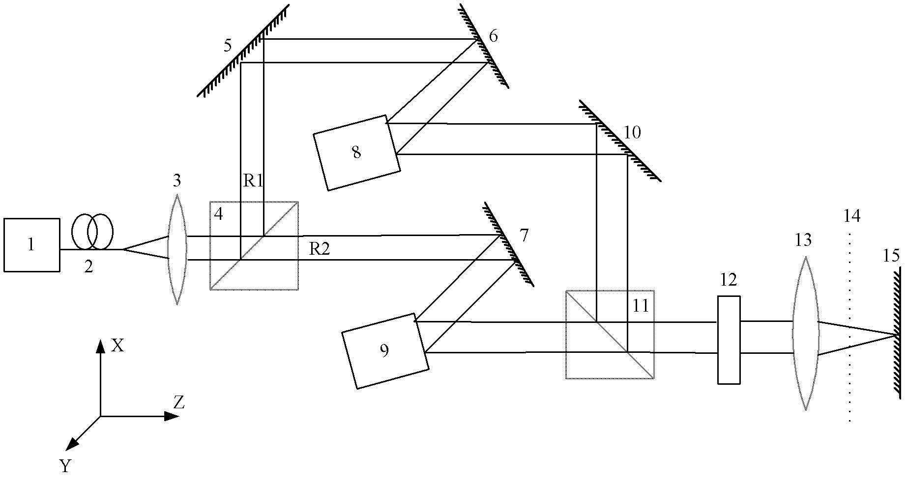
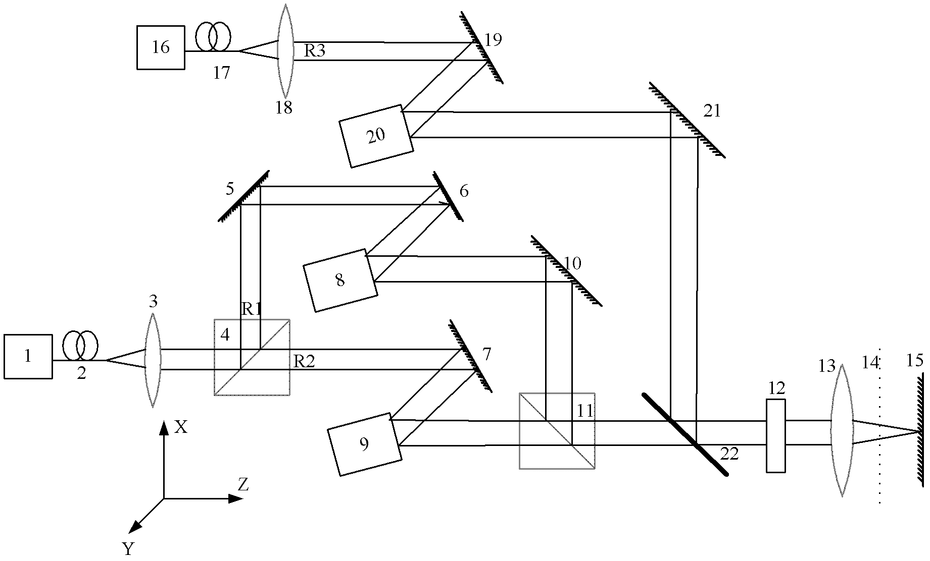
[0053] Such as figure 1 As shown, a three-dimensional hollow spot generating device includes: a first laser 1, a first single-mode fiber 2, a first collimator lens 3, a first polarization beam splitter prism 4, a first mirror 5, and a second mirror 6 , the third mirror 7, the first phase modulator 8, the second phase modulator 9, the fourth mirror 10, the second polarization beam splitter prism 11, 1 / 4 wave plate 12, microscope objective lens 13, sample surface 14, Dielectric film mirror 15.

[0054] Wherein, the first single-mode optical fiber 2 and the first collimating lens 3 are located on the optical axis of the beam emitted by the first laser 1, and the beam emitted by the first laser 1 is collimated to obtain a collimated beam; the first polarization splitting The prism 4 is located on the opt...


PUM


Abstract

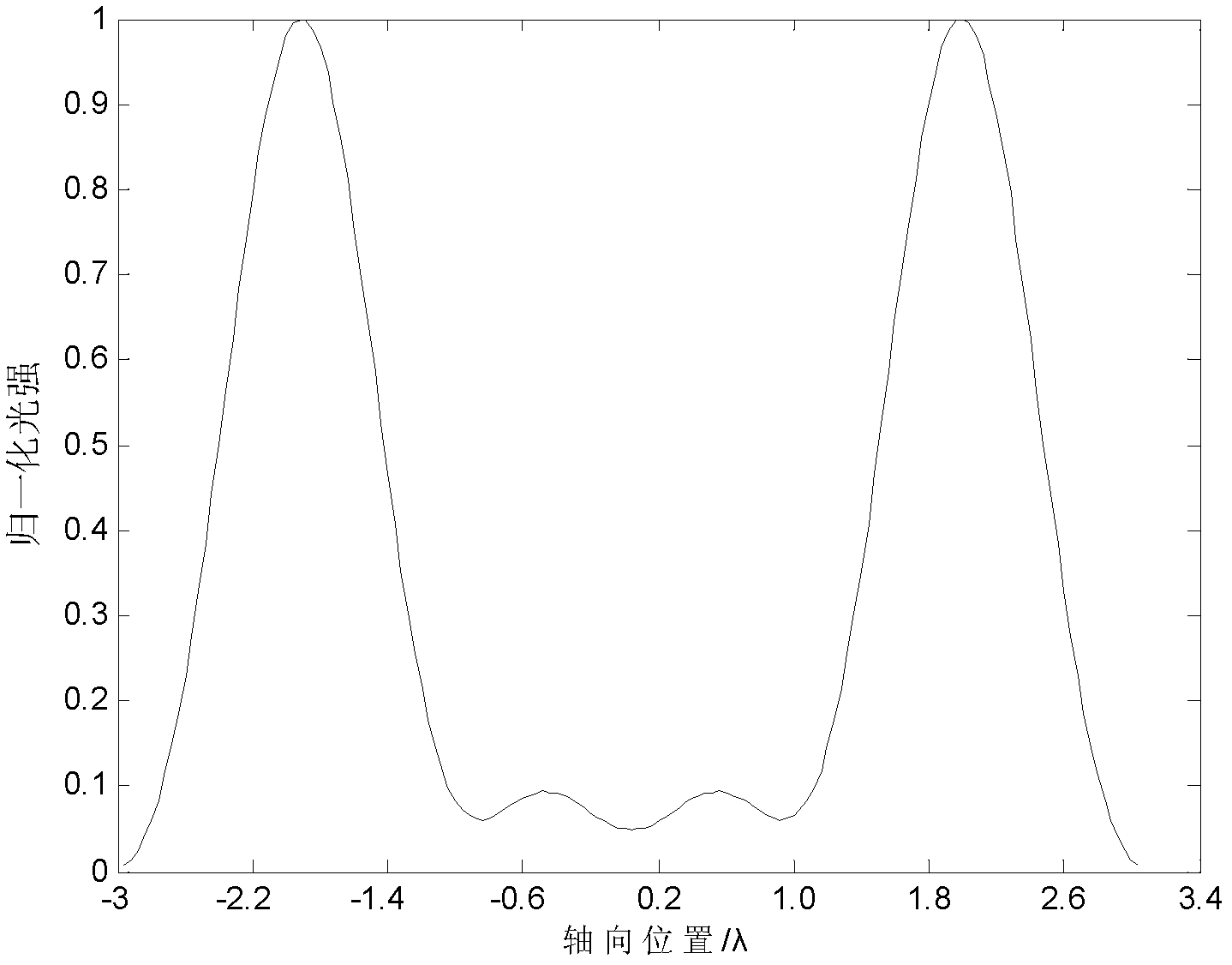
The invention discloses a three-dimensional hollow light spot generating method and a three-dimensional hollow light spot generating device. The three-dimensional hollow light spot generating device comprises a laser, a single mode fiber, a collimating lens, a first polarizing beam splitter prism, a plurality of light turning assemblies, two phase modulators, a second polarizing beam splitter prism, a 1 / 4 wave plate, a microobjective, a sample surface and a medium film reflecting lens. The three-dimensional hollow light spot generating method comprises the following steps; performing different phase modulation on vertical polarized light and parallel polarized light; combining the two modulated light beams, and converting the combined light beam into two circuit polarized lights by the same 1 / 4 wave plate; projecting the two circuit polarized lights by the microobjective to penetrate through the sample surface, and reflecting the two circuit polarized lights by the medium film reflecting lens; interfering the reflected light irradiated to the sample surface with projecting light to form a transverse hollow light spot and an axial hollow light spot respectively; and superposing the light intensities of the two hollow light spots to form a three-dimensional hollow light spot, wherein the transverse size of the three-dimensional hollow light spot is 0.56 wavelengths and the axial size of the three-dimensional hollow light spot is 0.44 wavelengths. The three-dimensional hollow light spot generating method and the three-dimensional hollow light spot generating device can be applied to super-resolution microscopic equipment such as a stimulated emission depletion microscope and are used for realizing three-dimensional super-resolution microscopy.

Description

technical field [0001] The invention belongs to the field of super-resolution microscopy, in particular to a method and device for generating a three-dimensional hollow spot. Background technique [0002] In super-resolution microscopy equipment such as stimulated emission depletion microscopy (STED: Stimulated Emission Depletion Microscopy), in order to realize three-dimensional super-resolution microscopy, it is necessary to generate a three-dimensional hollow spot. For the hollow spot, its size is defined as the distance between adjacent peaks on the light intensity distribution curve. Since the size of the generated 3D hollow spot will determine the resolution of the super-resolution system, how to generate a small-sized 3D hollow spot becomes the key to improving the resolution of the super-resolution system. [0003] With the development of science and technology, researchers have proposed a variety of methods to generate three-dimensional hollow spots. However, due ...

Claims


Application Information

Patent Timeline
IPC IPC(8): G02B27/09G02B27/28G02B17/06G02B21/18
Inventor 匡翠方李帅郝翔刘旭
Owner ZHEJIANG UNIV
Learn More