Double-layer air distribution method for fluidized bed dryer and equipment

A fluidized bed drying and fluidized air technology, which is applied in the directions of drying gas arrangement, drying solid materials, lighting and heating equipment, etc., can solve the problems of uneven fluidization, less material, dead bed, etc. Simple, less deadly effect

Inactive Publication Date: 2013-11-06
武汉钢铁有限公司
View PDF5 Cites 0 Cited by
  • Summary
  • Abstract
  • Description
  • Claims
  • Application Information

AI Technical Summary

Problems solved by technology

However, there are insurmountable defects in any air distribution method of the air distribution plate: the rotary mobile scraper is used to scrape the material, on the one hand, the large particle material is squeezed into the ventilation hole of the air distribution plate to block the air distribution plate, And it is prone to material leakage; on the other hand, uneven air distribution, large material accumulation on the moving direction side of the scraper, less material and small particles on the back side of the scraper, resulting in uneven fluidization and short circuit of hot air flow, resulting in dryness Poor effect and low thermal efficiency; on the other hand, the structure of the scraper machine is relatively complex, with many moving parts and high failure rate
This air distribution method reduces the direct contact between the material and the ventilation holes, and can prevent the ventilation holes on the air distribution pipe from being blocked by the material. Uniform state and fluidized dead angle, especially when the material to be dried contains larger particles, the larger particle material is easy to accumulate in the fluidized dead angle of the fluidized bed, and it is difficult to move from the feed port to the discharge port , which in severe cases will lead to deathbed

Method used


Image

  • Double-layer air distribution method for fluidized bed dryer and equipment
  • Double-layer air distribution method for fluidized bed dryer and equipment
  • Double-layer air distribution method for fluidized bed dryer and equipment

Examples


Embodiment Construction

[0021] The present invention will be further described in detail below in conjunction with the accompanying drawings and specific embodiments.

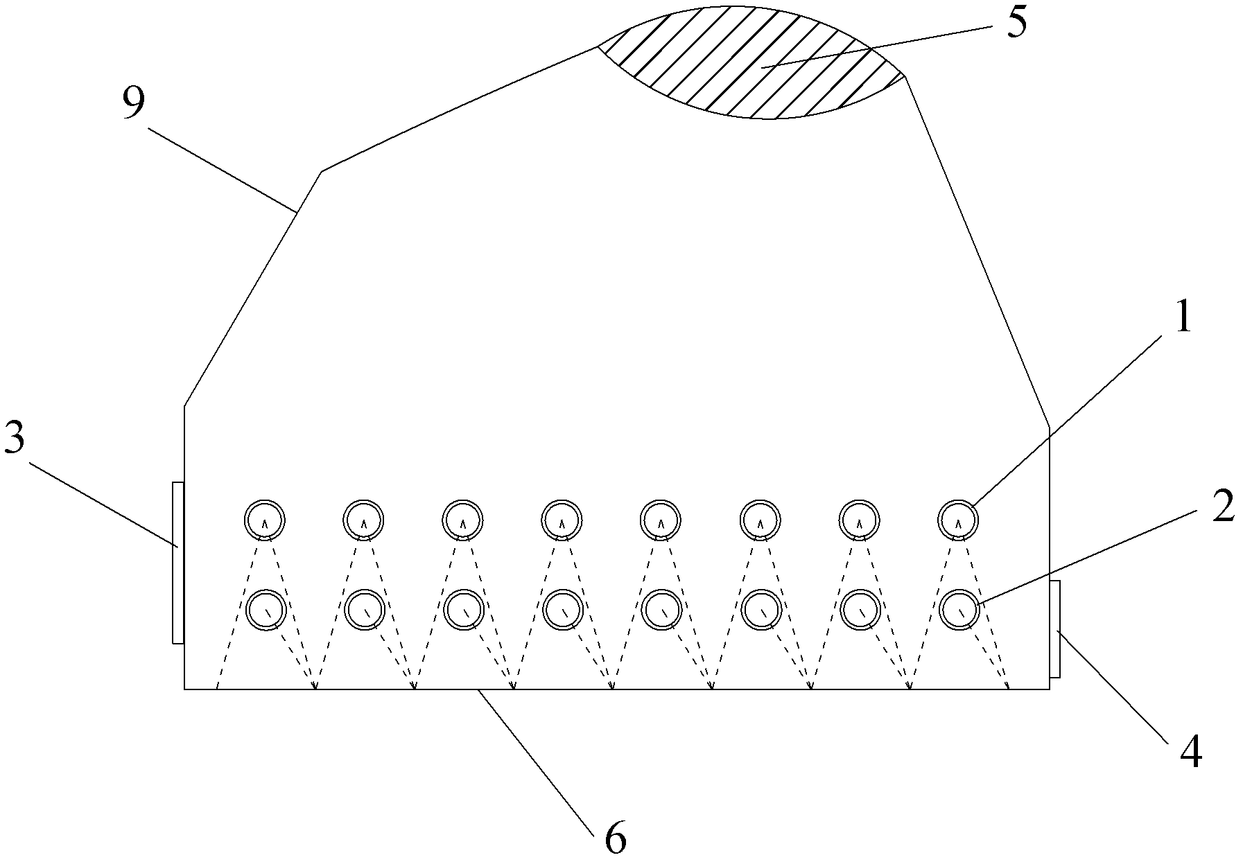
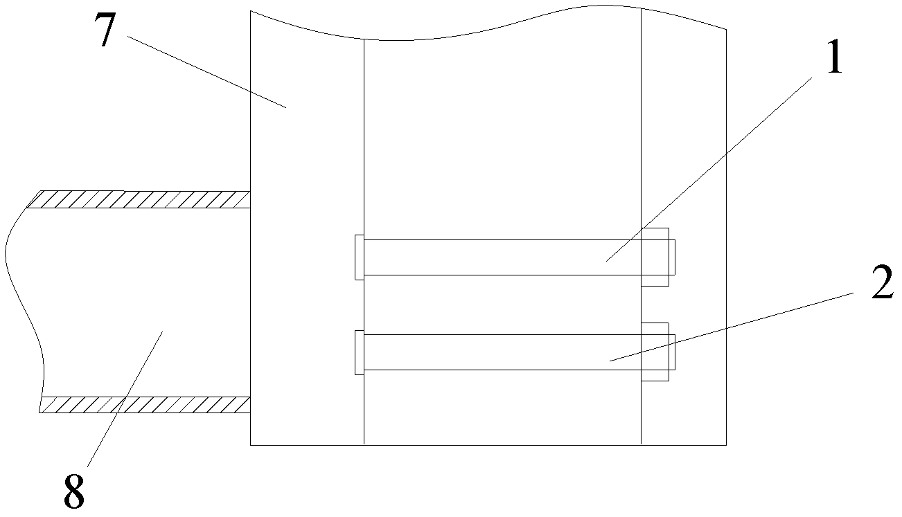
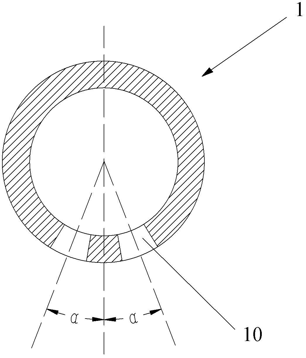
[0022] Such as Figure 1~6 As shown, the present invention provides a fluidized bed dryer using a double-layer air distribution method. It includes a fluidization chamber 9, the two ends of the fluidized bed bottom plate 6 of the fluidization chamber 9 are respectively provided with a feed port 3 and a discharge port 4, the top of the fluidization chamber 9 is provided with a powder outlet 5, the fluidization chamber 9 An air chamber 7 is arranged on the side, and the air chamber 7 is connected with the total air inlet pipe 8 . In the fluidization chamber 9, a row of upper-layer air distribution pipes 1 and a row of lower-layer air distribution pipes 2 connected to the air chamber 7 are arranged horizontally between the feed port 3 and the discharge port 4, and a row of upper-layer air distribution pipes 1 and A row of lower-layer a...


PUM


Abstract

The invention discloses a double-layer air distribution method for a fluidized bed dryer and the fluidized bed dryer. The method comprises that: a row of upper air distribution pipes and a row of lower air distribution pipes are horizontally arranged in a fluidized chamber of the fluidized bed dryer and axially arranged in parallel, the fluidized air distributed by an air chamber and entering each upper air distribution pipe is downwards jetted along air jet nozzles on two axial sides, each lower air distribution pipe is arranged in an included angle area of two blasts of fluidized air jetted by the corresponding upper air distribution pipe, the fluidized air distributed by the air chamber and entering each lower air distribution pipe is obliquely downwards jetted along an air jet port on one axial side, and the air jet port faces the discharge hole of the fluidized chamber. According to the fluidized bed dryer using the method, the upper and lower layers of air distribution pipes form an air distribution system and make the material fluidize above the fluidized chamber and directionally move towards the discharge hole together, so that the problem that the big granular material cannot be moved from the feeding hole to the discharge hole is solved.

Description

technical field [0001] The invention relates to the technical field of drying solid bulk materials in industries such as metallurgy, chemical industry, and pharmacy, and specifically refers to a double-layer air distribution method for a fluidized bed dryer and equipment thereof. Background technique [0002] In the production process of metallurgy, chemical industry, pharmaceutical and other industries, there is a need to dry solid bulk materials. One of the commonly used drying equipment is a fluidized bed dryer. There are two methods of air distribution in the fluidized bed dryer: air distribution board and air distribution tube. [0003] When the air distribution plate is used to distribute the air, the material to be dried is dried by the fluidized wind on the air distribution plate, and moves from the inlet to the outlet. When the material contains solid particles with a large particle size, the large particles The material is scraped by the rotary mobile scraper set ...

Claims


Application Information

Patent Timeline
Patent Type & Authority Patents(China)
IPC IPC(8): F26B21/00F26B3/08
Inventor 鲍俊芳薛改凤陈鹏詹立志常红兵任玉明梁尚国项茹宋子逵张雪红张前香刘向勇秦新会
Owner 武汉钢铁有限公司
Why Eureka
Try Eureka