Purification device and method for strongly acidic components in exhaust gas

A purification device, strong acid technology, applied in separation methods, chemical instruments and methods, dispersed particle separation, etc., can solve the problems of large input cost, large area, large amount of gas, and large area, and achieve high chemical reaction. The effect of activity, high reaction rate and long service life

Active Publication Date: 2015-12-02
HEFEI UNIV OF TECH
View PDF6 Cites 8 Cited by
  • Summary
  • Abstract
  • Description
  • Claims
  • Application Information

AI Technical Summary

Problems solved by technology

The advantage of the scrubber is that it can process a large amount of gas and have high efficiency. The disadvantage is that it consumes a large amount of alkali and occupies a large area of ​​equipment. Especially for laboratories that emit a small amount of strong acid waste gas, the installation of the scrubber is not only in terms of input cost but also in terms of land occupation. There are big problems

Method used


Image

  • Purification device and method for strongly acidic components in exhaust gas
  • Purification device and method for strongly acidic components in exhaust gas

Examples


Embodiment 1

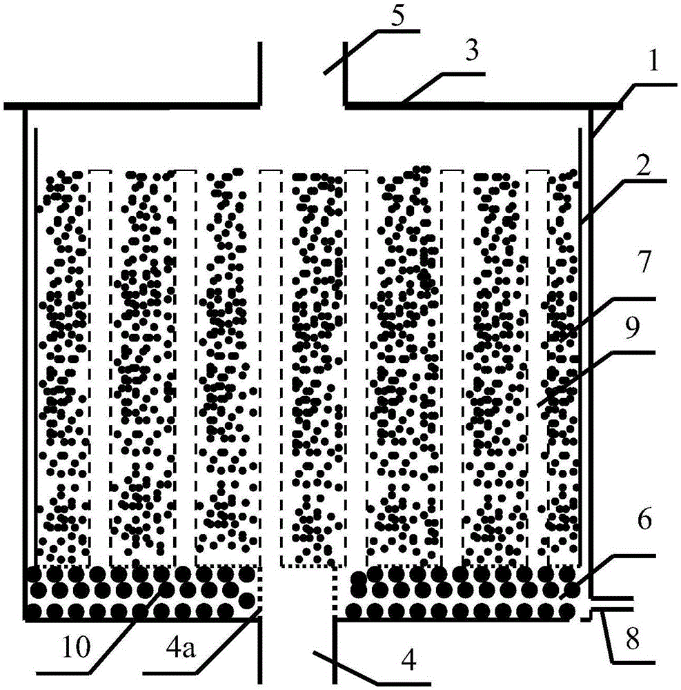
[0038] The structural schematic diagram of the vertical purification device of this embodiment is as follows figure 1 Shown:

[0039] The purification device of strongly acidic components in the exhaust gas is vertically placed with a plexiglass tube with a wall thickness of 4mm, an outer diameter of 300mm, and a height of 800mm as the reactor shell 1, and a plexiglass plate with a thickness of 5mm is used to make a disc with a diameter of 300mm, and Open a circular hole with a diameter of 50 mm in the center of the disc, and use acetone to dissolve the plexiglass powder as a binder to bond the plexiglass disc to the bottom of the above-mentioned plexiglass tube to form the bottom cover of the reactor shell. Gas inlet at the bottom of the reactor shell 1 .

[0040] Cut out a plexiglass tube with an outer diameter of 50 mm and a length of 300 mm, cut out 20 slits with a width of 3 mm and a length (along the radial direction of the plexiglass tube) of 40 mm at one end as the ga...

Embodiment 2

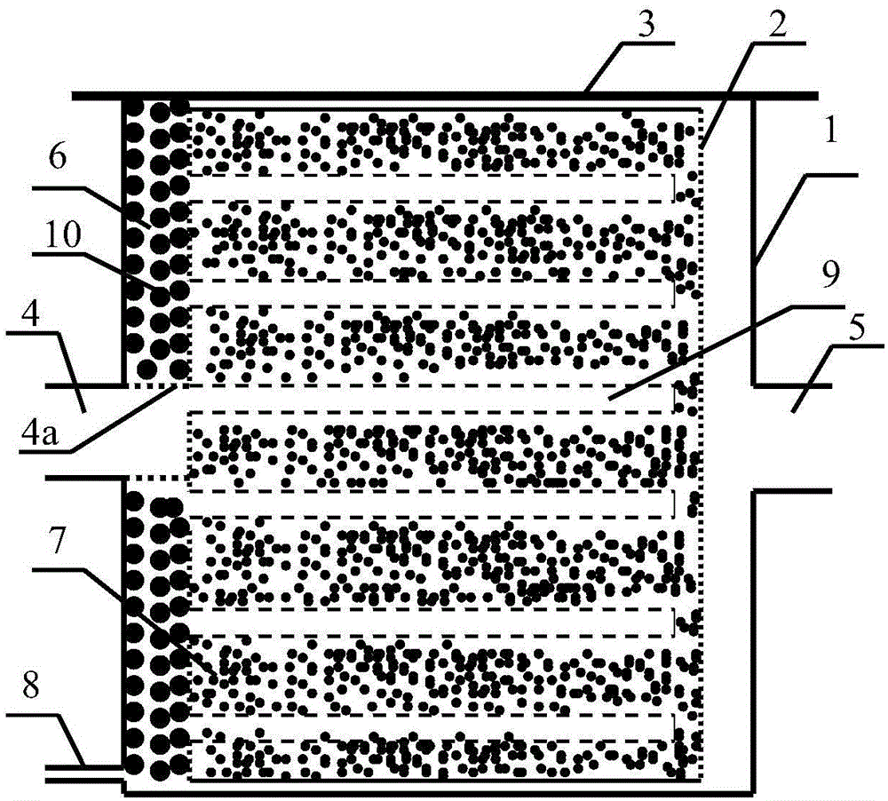
[0052] The schematic diagram of the structure of the flat-horizontal purification device in this embodiment is as follows: figure 2 Shown:

[0053] The purification device for strong acidic components in the exhaust gas uses a plexiglass plate with a thickness of 4mm to make a shell frame with a length of 500mm, a width of 300mm, and a height of 300mm. Use the same plexiglass plate to cut a 500mm×300mm plate and glue it to the above shell frame. As the bottom surface, the reactor shell 1 is formed. A circular hole with a diameter of 50 mm is opened on one side of the reactor shell as an air inlet, and a plexiglass tube with an outer diameter of 50 mm and a length of 300 mm is cut out at one end with a saw blade at a uniform interval of 3 mm in width and a length (along the plexiglass tube). 20 slits of 40 mm in radial direction are used as gas distribution slits 4a, insert one end processed with gas distribution slits 4a into the air inlet of 50 mm above, and protrude 50 mm ...


PUM

PropertyMeasurementUnit
Particle sizeaaaaaaaaaa
Diameteraaaaaaaaaa

Abstract

The invention discloses a purification device and method for strongly acidic components in exhaust gas. The purification device is characterized by comprising a reactor shell, an active material filling container arranged in the reactor shell and a bearing layer arranged between the reactor shell and the active material filling container. The top of the reactor shell is sealed through a sealing cover plate. The reactor shell is provided with a gas inlet, a gas outlet and a liquid outlet. A gas guide pipe is inserted into the active material filling container. According to the purification device, the exhaust gas containing the strongly acidic components is distributed through the bearing layer, enters the gas guide pipe and then enters the active material filling container through gas holes distributed in the gas guide pipe to make contact with an active material, the strongly acidic components are reacted with the active material to form salt, and purified exhaust gas is exhausted through an exhaust pipe.

Description

1. Technical field [0001] The invention belongs to the technical field of environmental protection, and in particular relates to the purification technology of strong acidic gaseous pollutants in waste gas. 2. Background technology [0002] Various laboratories and industrial production workshops that use volatile acids often emit strong acid waste gas, mainly HCl, HF, HNO 3 And the anhydride gas molecule SO produced by the decomposition of the compound 2 , SO 3 , NO 2 , N 2 o 5 Wait. The strong acid substances in the exhaust gas not only cause great harm to human health, but also have strong corrosiveness, damage various electrical equipment, corrode various metal products, cause serious corrosion of doors and windows, and affect environmental cleanliness. [0003] At present, the purification technology for all kinds of strong acid pollutants discharged by enterprises mainly adopts scrubbers, and the strong acid gases are discharged up to the standard by spraying sod...

Claims


Application Information

Patent Timeline
IPC IPC(8): B01D53/82B01D53/40B01D53/60B01D53/68
Inventor 谢巧勤陈天虎朱承驻王继忠邱高何宏平
Owner HEFEI UNIV OF TECH
Why Eureka
Try Eureka