Implants comprising biodegradable metals and method for manufacturing the same
一种制造方法、植入物的技术,应用在骨植入物、脊柱植入物、关节植入物等方向,能够解决介面粘着强度限制等问题,达到优异介面强度、生物降解率轻易、优异介面粘着强度的效果
- Summary
- Abstract
- Description
- Claims
- Application Information
AI Technical Summary
Problems solved by technology
Method used
Image

Examples
example 1
[0053] Implant material made from pure magnesium
[0054] Manufacturing costs also increase exponentially due to the higher purity when high purity materials with low dopant content are used. Therefore, its commercial value deteriorates. In each example, in order to determine the dopant concentration of magnesium that can be used as an implant material, different amounts of iron and nickel were added during the manufacture of magnesium, and its corrosion characteristics were evaluated (hereinafter, the dopant concentration is 0.01% or less Magnesium, known as pure magnesium or 100% magnesium). First, each magnesium with different dopant concentrations is filled in a stainless steel (SUS304) crucible with an inner diameter of 50 mm, wherein ultra-pure reagent-grade magnesium (99.9999%) is mixed with the following iron and nickel in different contents: (1) 400ppm (0.04%) and 10ppm (0.001%); (2) 70ppm (0.007%) and 5ppm (0.0005%); (3) 10ppm (0.001%) and 35ppm (0.0035%). Next, i...
example 2
[0056] Manufacture of magnesium calcium alloy
[0057] A magnesium alloy is made by mixing magnesium and calcium. Among them, pure magnesium (purity 99.995%) containing dopant 10ppm (0.001%) iron and 35ppm (0.0035%) nickel is mixed with 0.8%, 5%, 10.5%, 23%, and 33% calcium respectively, and The mixed materials were respectively charged into a stainless steel (SUS304) crucible with an inner diameter of 50 mm. Subsequently, in order to prevent the magnesium alloy in the crucible from coming into contact with the air, the temperature of the crucible was increased to a range of about 700°C to 1000°C with a resistance heater while flowing argon gas around the periphery of the crucible to melt the magnesium alloy. The completely molten magnesium alloy is quenched to produce a solid magnesium alloy. The crucible is stirred to mix the elements in the molten magnesium alloy with each other. In addition, during quenching, the crucible is immersed in water to rapidly cool and harden ...
example 3
[0060] Manufacturing of Mg-Ca Alloy by Rapid Quenching by Gas Blowing
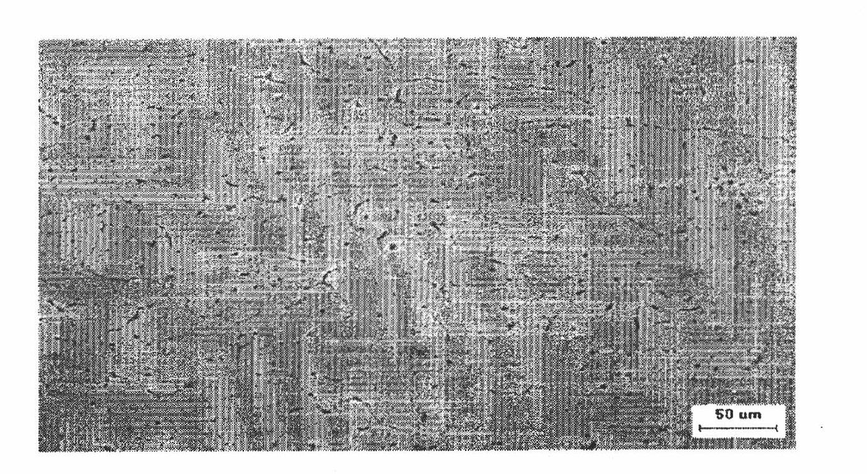
[0061] First, a heater is used to melt the magnesium alloy, and then the molten magnesium alloy is injected into a small hole with a diameter of about 3 mm by the spraying method using argon gas, and then solidified to form a rapidly quenched magnesium alloy Material. If this method is used, the rapid cooling and hardening rate of the magnesium alloy material is much higher than in Examples 1 and 2, thus exhibiting an extremely fine structure.
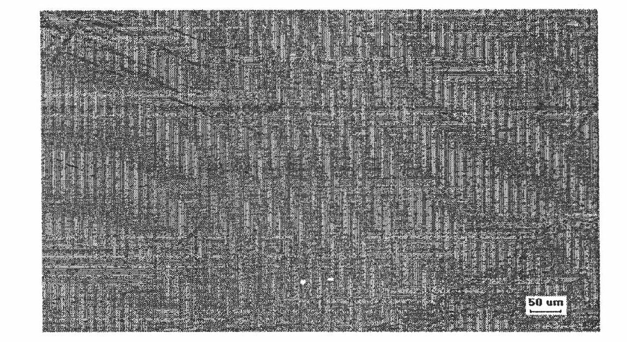
[0062] Figure 8 The photo shows Mg made by the above method 0.67 Ca 0.33 The cross-section of the alloy observed under an optical microscope, while Figure 7 It shows the cross-section of the magnesium alloy material made by immersing the crucible in water and quenching under an optical microscope. Compare Figure 8 and Figure 7 it can be discovered Figure 8 The size of the composite phase (composition phase) in is extremely fine.
PUM
 Abstract
Description
Claims
Application Information
 - Generate Ideas
- Intellectual Property
- Life Sciences
- Materials
- Tech Scout
- Unparalleled Data Quality
- Higher Quality Content
- 60% Fewer Hallucinations
Browse by: Latest US Patents, China's latest patents, Technical Efficacy Thesaurus, Application Domain, Technology Topic, Popular Technical Reports.
© 2025 PatSnap. All rights reserved.Legal|Privacy policy|Modern Slavery Act Transparency Statement|Sitemap|About US| Contact US: help@patsnap.com