Amorphous, microcrystalline or nano-crystalline alloy stator iron core for axial magnetic flux motor and manufacture method for stator iron core

A technology of nanocrystalline alloy and axial magnetic flux, which is applied in the manufacture of stator/rotor body, magnetic circuit static parts, magnetic circuit shape/style/structure, etc. Alloy motor iron core process is complex, etc., to improve production efficiency and iron core yield, save resin thermosetting molding treatment, and avoid the effect of soft magnetic performance decline

Active Publication Date: 2012-06-20
ADVANCED TECHNOLOGY & MATERIALS CO LTD
View PDF12 Cites 30 Cited by
  • Summary
  • Abstract
  • Description
  • Claims
  • Application Information

AI Technical Summary

Problems solved by technology

The amorphous alloy iron cores made by these two methods have air gaps at the joints, which affect the performance of the iron cores to a certain extent.
In 2004, the American Metgrass patent WO2004 / 070740 disclosed a method for preparing an amorphous stator core by photolithography and etching. This method is complicated in process and low in efficiency, and is not suitable for mass production.
In 2008, the invention patent CN101286676A of Antai Science and Technology Co., Ltd. disclosed a method for making stator iron cores by first heat-curing them into amorphous blocks and then cutting them as a whole. The technical foundation has been laid, but the size of the iron core is limited by the width of the amorphous alloy strip
The amorphous alloy iron core produced by this method is composed of multiple small amorphous blocks, and there is an air gap inside the iron core, and it is necessary to use an iron core holding part to combine the separated amorphous iron core blocks together, and the process is complicated
[0005] In summary, the existing technology for making amorphous alloy motor cores still has problems such as complex process, high cost, low yield and unsatisfactory performance.

Method used


Image

  • Amorphous, microcrystalline or nano-crystalline alloy stator iron core for axial magnetic flux motor and manufacture method for stator iron core
  • Amorphous, microcrystalline or nano-crystalline alloy stator iron core for axial magnetic flux motor and manufacture method for stator iron core
  • Amorphous, microcrystalline or nano-crystalline alloy stator iron core for axial magnetic flux motor and manufacture method for stator iron core

Examples


Embodiment 1

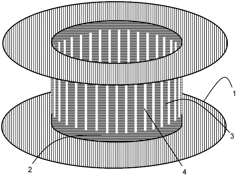
[0072] The nominal composition of the strip for making the axial flux amorphous alloy stator core is Fe 80 Si 9 B 11 (at.%), the thickness is 30±1μm, the width is 140mm, and the surface is smooth. The outer diameter of the amorphous alloy stator core to be produced is 180 mm, the inner diameter is 100 mm, the height is 40 mm, the slot depth is 30 mm, and the number of slots is 30. First, the amorphous alloy strip is rolled and cut into an amorphous alloy strip coil with a width of 80mm by rolling shearing equipment, and then the amorphous alloy strip with a width of 80mm is coiled twice to form a double amorphous alloy thin strip coil stand-by. Made of silicon steel sheets with a thickness of 0.5mm such as figure 1 The inner core of the iron core shown is composed of an annular bottom support 1 with an outer diameter of 180 mm and an inner diameter of 100 mm and a cylinder 2 with an inner diameter of 100 mm and a height of 80 mm. There are 30 inner core teeth 3 and 30 inn...

Embodiment 2

[0082] The rolling shearing, punching, coating, coiling and annealing treatment of the amorphous alloy strip are all the same as those in Example 1. That is, the amorphous alloy stator core made in embodiment 1 is subjected to a resin thermosetting treatment again. The specific process is as follows: the amorphous alloy stator core is immersed in the epoxy resin in the stainless steel tank, and put into the vacuum box together with the paint tank to evacuate to below 1Pa, and keep at this vacuum for 30 minutes. Then remove the vacuum environment, take out the amorphous alloy stator core and put it in an oven for thermal curing at 170°C. After 4 hours of heat preservation, turn off the power of the oven and let the amorphous alloy stator core cool down to room temperature naturally. So far, the axial magnetic flux amorphous alloy stator core processed by resin heat curing is completed.

[0083] The silicon steel core with the same specifications as the amorphous alloy stator c...


PUM

PropertyMeasurementUnit
Widthaaaaaaaaaa
Widthaaaaaaaaaa
Outer diameteraaaaaaaaaa

Abstract

The invention discloses an amorphous, microcrystalline or nano-crystalline alloy stator iron core for an axial magnetic flux motor and a manufacture method for the stator iron core. The manufacture method includes the steps: firstly, rolling and cutting a coiled amorphous, microcrystalline or nano-crystalline alloy wide band into an alloy strip coil (6) which is twice as high as that of the finished iron core, then uniformly punching a plurality of strip slots (17) in the middle of the alloy strip coil at intervals with the same equipment, performing insulation coating treatment and further coiling the alloy strip coil on an inner core (24) of the iron core, wherein the strip slots (17) are as same as open slots (26) in width, and the length of each strip slot (17) is twice of the depth of each open slot (26); next, adding an iron core outer-circumference protecting layer on the outer circumference face of the coiled alloy strip coil, then transversely halving the alloy strip coil into two identical alloy iron cores along the axial perpendicular plane of the alloy strip coil; and finally, carrying out high-temperature annealing treatment on the iron cores formed by processing. The stator iron cores prepared by the method are more excellent in performance, and particularly applicable to a high-speed motor, a high-power density motor and a high-torque density motor.

Description

technical field [0001] The invention belongs to the field of magnetic circuit components of motors, and in particular relates to an amorphous, microcrystalline or nanocrystalline alloy stator core for an axial flux motor and a manufacturing method thereof. The stator core is especially suitable for applications requiring high efficiency and energy saving High speed, high power density and high torque density motors. Background technique [0002] The motor is the electrical equipment with the highest power consumption in the world. Improving the efficiency of the motor is of great significance to energy saving, emission reduction, energy shortage and environmental pollution. At present, the improvement of motor efficiency is highly valued by countries all over the world. Many applications require not only high efficiency, but also high power density, high torque density or high speed, such as electric vehicles, aerospace, high-speed compressors, etc. The silicon steel core ...

Claims


Application Information

Patent Timeline
IPC IPC(8): H02K1/16H02K15/02
Inventor 周少雄张广强王立军李山红
Owner ADVANCED TECHNOLOGY & MATERIALS CO LTD
Why Eureka
Try Eureka