Fault removal method for multi-signal flow graph

A troubleshooting method, multi-signal technology, applied in the field of information to achieve the effect of reducing test time

Inactive Publication Date: 2012-04-25
CHENGDU QIANGFENG TECH
View PDF0 Cites 6 Cited by
  • Summary
  • Abstract
  • Description
  • Claims
  • Application Information

AI Technical Summary

Problems solved by technology

But in actual situations, tests with multiple output results will often appear, which requires implicit

Method used


Image

  • Fault removal method for multi-signal flow graph
  • Fault removal method for multi-signal flow graph
  • Fault removal method for multi-signal flow graph

Examples


Embodiment Construction

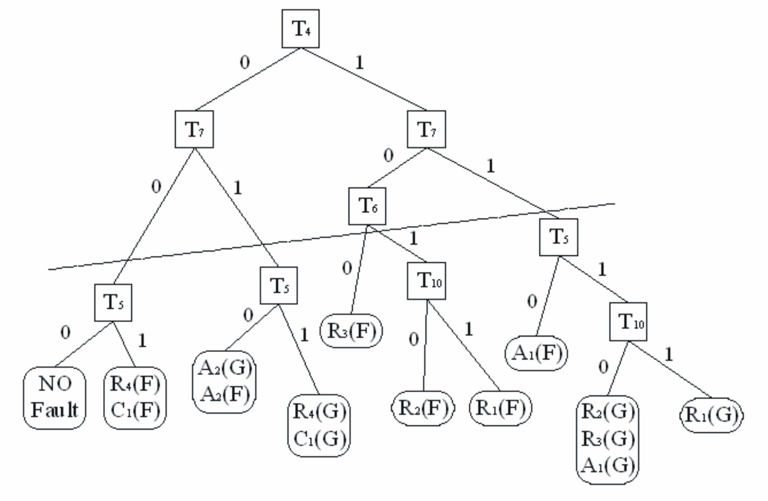
[0015] Test Partitioning Fault Isolation Method

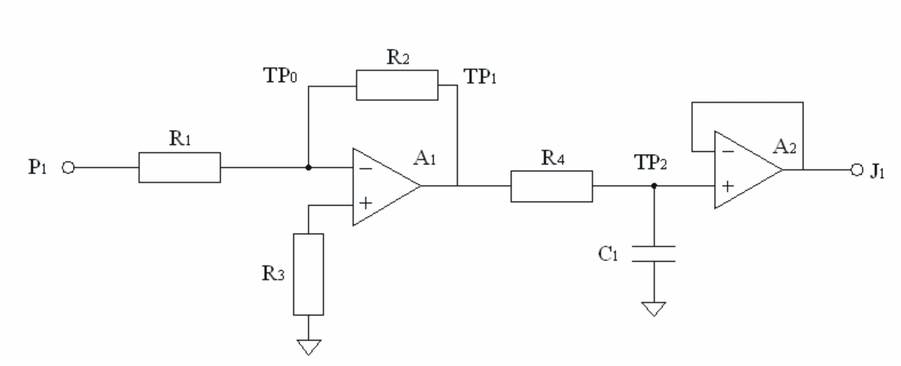
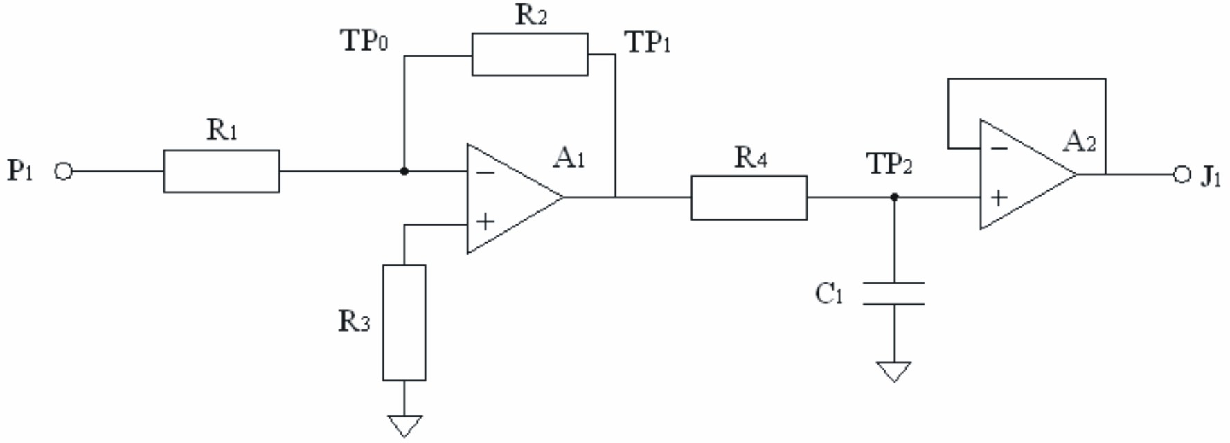
[0016] Take the filter amplifier circuit as an example to illustrate the process of using the multi-signal flow graph model for testing modeling. The circuit is shown in Figure 1.

[0017] Attribute signal associated with amplifier: S 1 is the gain, S 2 is linearity, S 4 is the signal slew rate, S 5 is the DC deviation; the property signal associated with the filter: , S 3 is the cut-off frequency; components that affect the signal of each attribute: resistance R 1 / / R 2 ≠R 3 , The linearity of the amplifier affects the signal S 5 , R 4 , C 1 Impact and S 3 , R 2 / R 1 and the amplifier's open-loop gain affect the preamplifier's gain, S 1 . Tests to detect each attribute signal:

[0018] 1) At the input P 1 Add a sine wave with a peak-to-peak value of 1 V and a frequency of 1 000 Hz at TP 1 point, to test the DC voltage, check the S 5 Test output voltage ratio, check S 1 ;Test Harmonic Distortion Che...


PUM


Abstract

The invention provides a fault removal method for a multi-signal flow graph. In a multi-signal flow graph model, tests for detecting the same attribute or with the same excitation can be simultaneously performed and are grouped accordingly, and in a fault removal process, a testing sequence is determined according to the probability of fault occurrences capable of being detected in each group, therefore the fault removal method based on test partition is developed. According to the method, the testing time is reduced to the largest extent; and the probability of fault occurrences and the lowest cost are both considered.

Description

technical field [0001] The invention relates to a troubleshooting method for a multi-signal flow graph, which belongs to the field of information technology. Background technique [0002] Previous modeling methods for fault diagnosis of complex systems include quantitative models, qualitative models, structural models and information flow models. Among them, the quantitative model and the qualitative model need to know the specific parameters of the system in advance, while the modeling of the structural model is relatively rough, and the information flow model has obvious deviations from the actual structure. In the information flow model, there are only two test results: pass or fail. But in actual situations, tests with multiple output results will often appear, which requires implicit [0003] processing, or formulating it as a series of tests of related binary outputs. For example, the voltage test may have three results: normal, high, and low. The test can be modele...

Claims


Application Information

Patent Timeline
Patent Type & Authority Applications(China)
IPC IPC(8): G01R31/28
Inventor 王烽杨素娟
Owner CHENGDU QIANGFENG TECH
Why Eureka
Try Eureka