
Power module and power conversion device

A power module and conversion technology, applied in the field of power conversion devices, can solve the problems of deterioration of insulation performance, low cooling performance, no sealing of internal electronic components, etc., and achieve the effect of improving insulation reliability.

Inactive Publication Date: 2012-04-11
HITACHI AUTOMOTIVE SYST LTD
View PDF11 Cites 20 Cited by
  • Summary
  • Abstract
  • Description
  • Claims
  • Application Information

AI Technical Summary

Problems solved by technology

[0006] In the structure disclosed in Patent Document 4, the heat dissipation surface of the power semiconductor is only one side, and there is a problem of low cooling performance.
In addition, there is no description about the sealing of the internal electronic components with respect to the cooling medium.
If the cooling medium permeates, the adhesive force of the insulating adhesive or the insulating performance of the insulating adhesive and the inorganic insulating layer itself deteriorates, and as a result, the insulating performance of the insulating substrate cannot be maintained.

Method used


Image

  • Power module and power conversion device
  • Power module and power conversion device
  • Power module and power conversion device

Examples


Embodiment 1

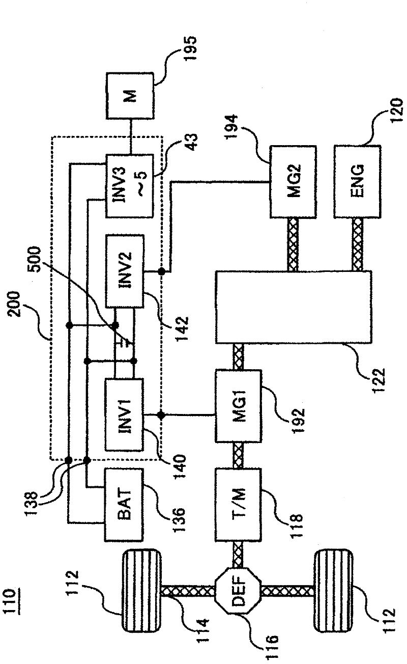
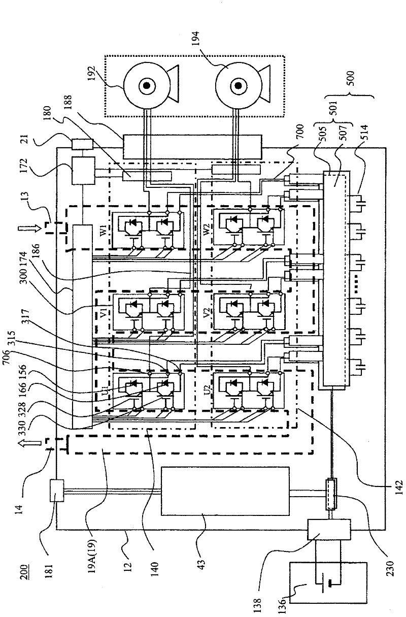
[0052] figure 1 is a diagram showing a control block of a hybrid vehicle. exist figure 1 Among them, a hybrid electric vehicle (hereinafter referred to as "HEV") 110 is one electric vehicle and includes two vehicle driving systems. One of the drive systems is an engine system that uses an engine 120 as an internal combustion engine as a power source. The engine system is mainly used as a driving source of HEV 110 . Another driving system is an on-vehicle motor system using motor generators MG1 192 and MG2 194 as power sources. The on-vehicle motor system is mainly used as a drive source of HEV 110 and a power generation source of HEV 110 . The motor generators MG1 192 and MG2 194 are, for example, synchronous machines or induction machines, and operate as electric motors or generators depending on the method of operation, so they are referred to as motor generators here.

[0053] The front wheel axle 114 is rotatably supported at the front of the vehicle body. A pair of ...

Embodiment 2

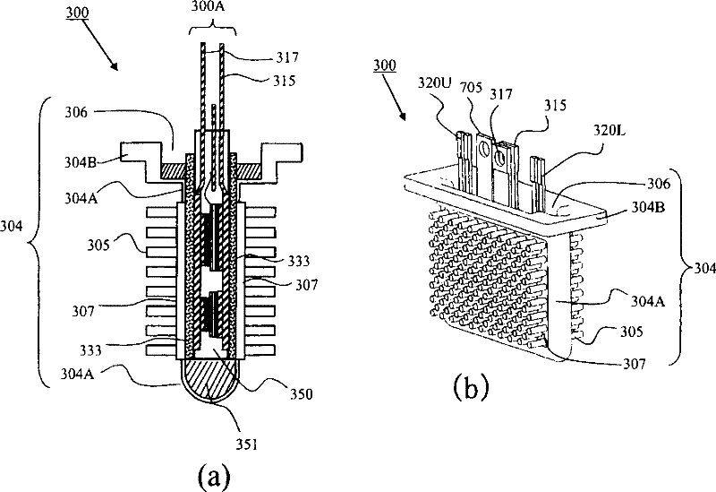
[0139] Figure 11 (a) is a cross-sectional view of a power module 300 according to another embodiment, Figure 11 (b) is an exploded cross-sectional view of a power module 300 according to another embodiment. Hereinafter, parts different from those of the first embodiment will be described, and the configurations assigned the same symbols as those of the first embodiment have the same functions.

[0140] In this embodiment, an aluminum insulating plate 340 is disposed instead of the insulating sheet 333 according to the first embodiment. Adhesive thin resin insulating layers 342 are formed on both main surfaces of the aluminum insulating plate 340 . The alumina plate 341 is sandwiched between two resin insulating layers 342, and the whole is treated with alumina to form alumina layers 601 on the front and back surfaces. The alumina plate 341 and the two resin insulating layers 342 are bonded by thermocompression.

[0141] The module primary sealing body 300A is firmly bond...

Embodiment 3

[0149] Figure 16 (a) is a cross-sectional view of a power module 300 according to another embodiment, Figure 16 (b) is a sectional view at the time of assembly of the power module 300 according to another embodiment. Hereinafter, parts different from those of the first embodiment will be described, and the configurations assigned the same symbols as those of the first embodiment have the same functions.

[0150] In this embodiment, flow path forming bodies 380A and 380B in which a flow path 381 is formed inside are used instead of the can cooler 304 according to the first and second examples. Such as Figure 16 As shown in (b), the alumina treatment described in Example 1 was performed on the surfaces 382A and 382B of the flow channel forming bodies 380A and 380B that are in contact with the insulating sheet 333 .

[0151] Accordingly, it is not necessary to form the organic acid-based alumina layer 601B on the inner flat surface 308 of the can cooler 304 as shown in the ...


PUM


Abstract

A power module according to the present invention includes: a semiconductor element for converting DC current to AC current by switching operation; an electrical wiring board to which the semiconductor element is electrically connected, with the semiconductor element being disposed upon one of its principal surfaces; an insulating resin layer provided on the other principal surface of the electrical wiring board; a first insulation layer that is disposed opposite from the electrical wiring board, separated by the insulating resin layer, and that is joined to the insulating resin layer; a second insulation layer that is disposed opposite from the insulating resin layer, separated by the first insulation layer, and that ensures electrical insulation of the semiconductor element; and a metallic heat dissipation member that is disposed opposite from the first insulation layer, separated by the second insulation layer, and that radiates heat generated by the semiconductor element via the electrical wiring board, the insulating resin layer, the first insulation layer, and the second insulation layer.

Description

technical field [0001] The present invention relates to a power module with a built-in inverter circuit, and a power conversion device including the power module. Background technique [0002] Patent Documents 1 to 3 disclose structures of conventional double-sided cooling power modules, in which electrical wiring, an insulating layer, and a cooler are disposed on one main surface of a built-in power semiconductor element on which electrodes are formed, and on the other main surface. Electrical wiring, insulating layers and coolers are similarly arranged on the surface. In addition, in the above-mentioned cooler, the heat dissipation base and the heat dissipation fins are formed on the surface opposite to the arrangement surface of the power semiconductor elements, and the cooler is inserted and immersed in the cooling surface formed with the internal space sealed by the resin material. In the waterway frame of the waterway, the cooling medium is in direct contact with the ...

Claims


Application Information

Patent Timeline
Patent Type & Authority Applications(China)
IPC IPC(8): H01L23/367H02M7/00H02M7/48B60L50/15B60L50/16
CPCY02T10/6217B60L2200/32B60L2220/12H02M7/003B60L2200/10B60L2240/525H01L2224/83101H01L23/467H01L2224/8384B60K6/445H01L2924/13091B60L2240/36Y02T10/70H01L23/367B60L11/123Y02T10/6239B60L2200/26H01L24/33B60L3/003B60K6/365H01L23/433B60K1/02H01L25/072B60L11/14Y02T10/7077H01L2224/73265B60L2200/36B60L2220/14H01L2924/01327H01L2924/13055H01L2924/07802H01L2924/1306H01L2924/1305H01L2924/181C25D11/08C25D11/10C25D11/12H01L23/473B60L50/61B60L50/16Y02T10/62Y02T10/7072H01L2924/00
Inventor 德山健中津欣也斋藤隆一佐藤俊也石川秀明
Owner HITACHI AUTOMOTIVE SYST LTD
Learn More