
Special bracket for continuously casting long nozzle

A shroud and bracket technology, which is applied to casting equipment, casting melt containers, metal processing equipment, etc., can solve the problems of unsuitable shrouds, etc., and achieve the effect of good flexibility and convenient loading, unloading and replacement

Inactive Publication Date: 2014-06-25
SHANGHAI MEISHAN IRON & STEEL CO LTD
View PDF1 Cites 0 Cited by
  • Summary
  • Abstract
  • Description
  • Claims
  • Application Information

AI Technical Summary

Problems solved by technology

But this bracket is for the quick replacement of the submerged nozzle of the crystallizer, not suitable for the long nozzle

Method used


Image

  • Special bracket for continuously casting long nozzle
  • Special bracket for continuously casting long nozzle
  • Special bracket for continuously casting long nozzle

Examples


Embodiment 1

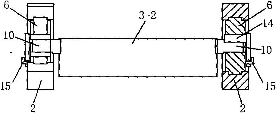
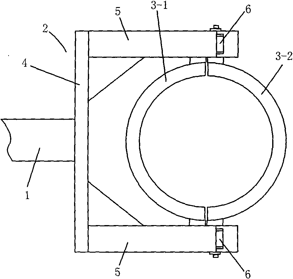
[0036] The special bracket for continuous casting shroud in this embodiment is as follows: figure 1 , figure 2 and image 3 As shown, it includes a support platform 2 arranged at the end of the manipulator cantilever 1 and support rings 3-1 and 3-2 divided into two halves. The support platform 2 is mainly composed of a base plate 4 and two support plates symmetrically fixed on both sides of the base plate 4 5 forms the C font that surrounds one 3-1 of two half support circles. Such as figure 1 and Figure 4 As shown, one end of supporting plate 5 is made into a Y-shaped opening, and a rotating seat 6 is stuck in the Y-shaped opening. Such as Figure 4 and Figure 5 Shown, be shaped on arc groove 7 in Y font opening; Figure 6 and Figure 7 As shown, the outer surface of the rotating seat 6 is formed with an arc-shaped convex line 8 matching the arc-shaped groove 7 . Such as Figure 4 and Figure 6 As shown, the minimum outer diameter D of the rotating seat 6 1 Sma...

Embodiment 2

[0040] The special bracket for the continuous casting shroud in this embodiment is an improvement on the basis of the first embodiment, except that it is the same as the first embodiment except that the structure of the pin 14 is replaced by a new pin 16 . New latch 16 as Figure 16 and Figure 17 As shown, the new pin 16 is also formed L-shaped by the new pin shaft 16-1 and the new pin handle 16-2 that intersect perpendicularly. The difference between the new pin 16 and the pin 14 of embodiment one is: 1) the new pin shaft 16-1 Section is big semicircle (certainly also can be small semicircle, positive semicircle or near semicircle etc.), the section of new bearing pin 16-1 is less than or equal to the section of the second half slot 12 and greater than the first The section of half slot 11; 2) new pin handle 16-2 bottom is shaped on a gap 17, can limit new bearing pin 16-1 to rotate counterclockwise. When the new latch 16 of the present embodiment is assembled as Figure ...


PUM


Abstract

The invention relates to a special bracket for continuously casting a long nozzle, belonging to the technical field of metal casting tools. The special bracket comprises a supporting table arranged at the end part of a manipulator cantilever and a supporting ring which is divided into two half supporting rings, wherein the supporting table forms a C shape enclosing one of the two half supporting rings mainly by a base plate and two supporting plates symmetrically fixed at two sides of the base plate; one ends of the supporting plates are made into a Y-shaped opening in which a rotating seat is clamped, the supporting ring is movably connected with the rotating seat, an arc-shaped groove is arranged in the Y-shaped opening, an arc-shaped raised line matched with the arc-shaped groove is arranged on the outer surface of the rotating seat, the minimum external diameter of the rotating seat is smaller than the minimum caliber of the Y-shaped opening, and the minimum caliber of the Y-shaped opening is smaller than the diameter of the arc-shaped groove. The special bracket is free of influence of high temperature and steel slag and can effectively realize free swing when being repeatedly and accurately butt-jointed with a bale after the long nozzle is hooped and fixed by the supporting ring.

Description

technical field [0001] The invention relates to a bracket for fixing a continuous casting shroud, which belongs to the technical field of metal casting tooling. Background technique [0002] During continuous casting, it is necessary to continuously inject molten metal from the steel tank (also called the ladle) into the tundish through the long nozzle (also called the ladle long nozzle). The long nozzle is generally moved by a manipulator, and the front end of the cantilever of the manipulator is equipped with a bracket. Used to install long nozzles. There are two important technological requirements for the shroud in actual use: first, it is required to be able to swing freely (that is, have good flexibility) when it is docked with the ladle, so as to ensure a good connection between the shroud and the ladle to prevent backfilling of molten steel Or gas inhalation, so as to ensure the quality of continuous casting; second, the shroud is required to be easily disassembled,...

Claims


Application Information

Patent Timeline
Patent Type & Authority Patents(China)
IPC IPC(8): B22D41/56
Inventor 罗家志夏兆东杨金成于小春陈志华李玉华赵兴勇
Owner SHANGHAI MEISHAN IRON & STEEL CO LTD
Learn More