Special polishing disc for deburring machine and manufacturing method thereof

A technology for deburring machines and polishing discs, applied in grinding/polishing equipment, manufacturing tools, abrasives, etc., can solve the problems of poor abrasive straightness, poor quality, affecting service life, etc., and achieve good abrasive straightness and service life. Long, ensure the effect of deburring

Active Publication Date: 2015-10-07
HANGZHOU XIANGSHENG ABRASIVE MACHINE MFG
View PDF7 Cites 0 Cited by
  • Summary
  • Abstract
  • Description
  • Claims
  • Application Information

AI Technical Summary

Problems solved by technology

Its shortcomings: First, it is impossible to ensure the flatness of the planted abrasive head surface, resulting in uneven planting surface, which directly affects the deburring effect; second, the planting is poor in straightness, because the abrasive head is fixed at the root and is located in the polishing disc shell. There is no supporting point in the non-polishing part of the groove, so the abrasive is poor in uprightness and easy to fall, which directly affects its service life; the third is low planting efficiency, high cost, and poor quality

Method used


Image

  • Special polishing disc for deburring machine and manufacturing method thereof
  • Special polishing disc for deburring machine and manufacturing method thereof
  • Special polishing disc for deburring machine and manufacturing method thereof

Examples


Embodiment 1

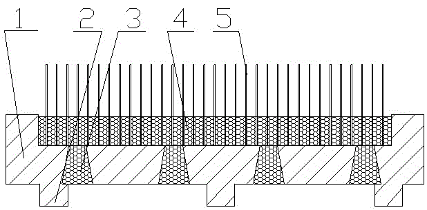
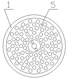
[0013] Example 1: Refer to the attached figure 1 with 2 . A special polishing disc for a deburring machine, which includes a polishing disc shell 1 and an abrasive head 5. The polishing disc shell 1 has a circular groove structure, and the bottom of the circular groove has a plurality of tapered column holes 3; The abrasive head 5 is located in the circular groove and in the circular groove and the tapered hole is a resin solidified body 4 (epoxy resin solidified body). The diameter of the conical resin solidified body in the conical hole is small at the top and large at the bottom. The back of the polishing disk shell 1 is provided with one or more rings of reinforcing ribs 2 and is an integral structure with the polishing head shell 1. An annular boss is arranged around the central mounting screw hole of the polishing disk shell 1, and the ring boss and the groove bottom of the mounting screw hole form an annular convex groove.

Embodiment 2

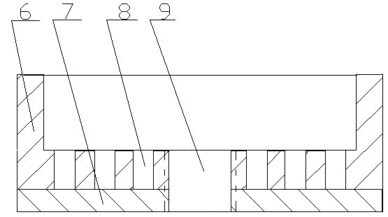
[0014] Example 2: Refer to the attached image 3 with 4 . A special polishing disk forming mold for deburring machine, which is composed of a forming die ring 6, a die bottom plate 7 and a planting core 8. The die bottom plate 7 is fixed on the circumferential end surface of the die ring 6 and constitutes a polishing disk molding frame. The die bottom plate 7 is opened in the center. There is an ejection screw hole 9, the planting mold core 8 is located in the polishing disk forming mold frame, and the ejection bolt is screwed into the ejection screw hole 9. The planting mold core 8 has multiple planting holes and is covered with a molding frame. The planting holes are round holes, rectangular holes, oblique strip holes, and sheet mounting holes, and the holes are separated by partitions.

Embodiment 3

[0015] Example 3: On the basis of Examples 1 and 2, a method for manufacturing a special polishing disc for a deburring machine. (1) The planting core 8 is selected according to the shape of the abrasive, and the planting core 8 is placed in the special polishing disc for the deburring machine The polishing disk of the forming mold is formed in the molding frame, and then the abrasive is inserted into the planting hole of the planting core 8 and the insertion end of the abrasive is in contact with the mold bottom plate 7; (2) Use non-stick tape to concave the special polishing disk for the deburring machine The tapered hole of the groove is glued from the outside, and a limit steel plate is placed in the annular convex groove of the polishing disc forming mold for the deburring machine. Due to the caliber of the polishing disc shell 1 for the deburring machine and the polishing disc forming mold for the deburring machine The caliber is the same, so buckle the polishing disc form...


PUM


Abstract

The invention relates to a special polishing plate for a deburring machine and a manufacturing method thereof, and the special polishing plate is used for ensuring the consistent evenness of the end face of a polishing head in the special polishing plate for the deburring machine while realizing the quick planting for a grinding material head. The polishing plate comprises a polishing plate shell and a grinding material head, wherein the polishing plate shell is of a circular groove structure; a plurality of conical pillar holes are formed at the bottom of a circular groove; and the grinding material head is located in the circular groove and solidified resins are arranged in the circular groove and the conical pillar holes. The special polishing plate for the deburring machine has the following advantages: 1) the evenness and height of the end face of a planted grinding material head are kept consistent, and the deburring effect is ensured; 2) the planted straight degree is high, and a planting hole for planting a mold core is fixed at the root of the grinding material head and the upper part of the root of the grinding material head is fixed by resins, so that a non-polishing part in the groove of the polishing plate shell has a resin supporting point, the straight degree of a grinding material in the grinding material head is high, the grinding material never falls off and the service life is long; and 3) the planting efficiency is high, the cost is low and the quality is high.

Description

Technical field [0001] The invention relates to a special polishing disc for a deburring machine and a manufacturing method that can ensure the uniformity of the end surface of the polishing head in the special polishing disc for the deburring machine and realize rapid planting of abrasive heads and a manufacturing method, belonging to the field of polishing head manufacturing. Background technique [0002] At present, the method for making polishing discs for deburring machines at home and abroad is to make planting counterbores or planting grooves in the polishing disc shell according to the shape of the abrasive head, and then insert multiple abrasive heads or multiple abrasive pieces into the planting counterbores Or after planting the groove, use epoxy resin to cast the planting counterbore or planting groove. Its shortcomings: First, it can neither ensure the flatness of the planted abrasive head surface, which causes the planting surface to vary in height, which directly a...

Claims


Application Information

Patent Timeline
Patent Type & Authority Patents(China)
IPC IPC(8): B24D7/00B24D3/28B24D18/00
Inventor 陈勇奇
Owner HANGZHOU XIANGSHENG ABRASIVE MACHINE MFG
Why Eureka
Try Eureka