
Contact pin movement mechanism for thermistor material strips

A thermistor and moving mechanism technology, applied in the direction of resistors with negative temperature coefficient, resistors with positive temperature coefficient, etc., can solve the problems of unable to continue to move, the material belt is stuck, etc., to improve work efficiency, overcome the overlapping effect

Active Publication Date: 2012-02-08
SUZHOUSCON AUTOMATION TECH
View PDF3 Cites 0 Cited by
  • Summary
  • Abstract
  • Description
  • Claims
  • Application Information

AI Technical Summary

Problems solved by technology

[0002] When the pin is inserted into the process hole of the thermistor strip, the previous thermistor strip pushes the next thermistor strip to move, and the thermistor strip pushes the next one, which makes it impossible to continue to move due to the thickness of the strip. If it is relatively thin and there is a gap between the upper and lower cover plates, the two thermistor strips will overlap, eventually causing the strips to get stuck, making it impossible to continue moving

Method used


Image

  • Contact pin movement mechanism for thermistor material strips
  • Contact pin movement mechanism for thermistor material strips

Examples


Embodiment Construction

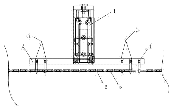
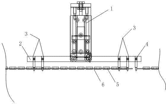
[0009] Such as figure 1 As shown, the thermistor material has a pin moving mechanism, and a pin fixing plate 2 is suspended on the lower end of the pin moving mechanism 1 through rollers, and the two tail ends of the pin fixing plate 2 are respectively fixed with first pins at equal intervals. Pin 3 is provided with a thermistor strip 5 at the lower end of the pin fixing plate 2, the thermistor strip 5 is segmented, and each section of thermistor strip 5 is provided with a plurality of process holes 6, each The distance between the process holes 6 is equal to the distance between the first pins 3 at intervals, and the second pin 4 is fixed on one end of the pin fixing plate 2, the second pin 4 and the first pin 3 The distance between them is equal to the distance between the first pins 3 , and the second pins 4 are located between the end of the previous thermistor strip 5 and the head end of the next thermistor strip 5 .

[0010] In specific applications, after the pin movin...


PUM


Abstract

The invention provides a contact pin movement mechanism for thermistor material strips. A contact pin fixing plate is suspended at the lower end of the contact pin movement mechanism through a trolley wheel; a first contact pin is respectively fixed at two tail ends of the contact pin fixing plate in equal distance; thermistor material strips in sectional type is arranged at the lower end of the contact pin fixing plate; a plurality of processing holes are arranged on each section of thermistor material strip; the distance between the processing holes is equal to that between the interval first contact pins; a second contact pin is fixed at one tail end of the contact pin fixing plate; the distance between the first contact pin and the second contact pin is equal to a gap between the first contact pins; and the second contact pin is located between the tail end of the previous thermistor material strip and the front end of the next thermistor material strip. Because the second contactpin is arranged, the conditions of overlapping and clamping of the two thermistor material strips in the movement process can be overcome, and the working efficiency is improved.

Description

technical field [0001] The invention relates to a moving mechanism of a thermistor strip pin. Background technique [0002] When the pin is inserted into the process hole of the thermistor strip, the previous thermistor strip pushes the next thermistor strip to move, and the thermistor strip pushes the next one, which makes it impossible to continue to move due to the thickness of the strip. If it is relatively thin and there is a gap between the upper and lower cover plates, the two thermistor strips will overlap, eventually causing the strips to get stuck and unable to move further. Contents of the invention [0003] The purpose of the present invention is to overcome the deficiencies in the prior art, and provide a thermistor strip pin moving mechanism. [0004] The purpose of the present invention is achieved through the following technical solutions: [0005] The thermistor material has a pin moving mechanism, and a pin fixing plate is suspended by rollers at the lo...

Claims


Application Information

Patent Timeline
Patent Type & Authority Applications(China)
IPC IPC(8): H01C7/02H01C7/04
Inventor 曾航
Owner SUZHOUSCON AUTOMATION TECH
Learn More