
Prefabricated cast-in-place combination type superposed shear wall

A technology of superimposed shear walls and shear walls, applied to walls, building components, buildings, etc., can solve the problems of unsatisfactory industrialized residential walls and housing shortages, and achieve the improvement of drawing strength, reduction of high-altitude operations, good safety effect

Inactive Publication Date: 2012-02-01
沈阳万科企业有限公司
View PDF6 Cites 9 Cited by
  • Summary
  • Abstract
  • Description
  • Claims
  • Application Information

AI Technical Summary

Problems solved by technology

[0002] After the 1950s, the United States, Western Europe, and Japan, with post-war reconstruction, rapid economic development, technological progress, substantial population growth, demobilization of soldiers, and influx of immigrants, all experienced serious housing shortages, which could not be met by traditional housing construction methods. this need
Commonly used prefabricated components for industrialized housing include prefabricated exterior wall panels, prefabricated balconies, prefabricated stairs, and prefabricated floors. Among them, prefabricated exterior wall panels are the core and difficulty of the entire industrialized technology system. Mainly, there are no walls and other materials that meet the needs of industrialized housing

Method used


Image

  • Prefabricated cast-in-place combination type superposed shear wall
  • Prefabricated cast-in-place combination type superposed shear wall
  • Prefabricated cast-in-place combination type superposed shear wall

Examples


Embodiment 1

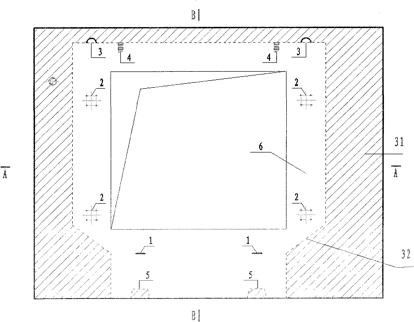
[0044] Such as Figure 1 to Figure 6 Shown is a shear wall structure with a window, including an outer wall 7, an insulating material layer 8, and an inner wall 6, and the insulating material layer 8 is interposed between the outer wall 7 and the inner wall 6 Between, the inner leaf wall 6 and the outer leaf wall 7 are connected by a connector 30, the inner leaf wall 6 is composed of two parts, one part is a prefabricated part, and the other part is a cast-in-place part 31, and the inner leaf wall 6 The prefabricated part is located in the middle part of the outer leaf wall 7, and the area of ​​the prefabricated part of the inner leaf wall 6 is smaller than the outer leaf wall 7 to reserve the space of the cast-in-place part, the inner leaf wall 6 and the outer leaf wall 7 and The insulation material layer 8 reserves the position of the window, and the window frame is made into one with the prefabricated part; as Figure 4 ~ Figure 6 As shown, the prefabricated part of the in...

Embodiment 2

[0052] Figure 7 ~ Figure 10It is another kind of embodiment of the present invention, and the difference between this embodiment and embodiment 1 is: the shear wall does not have reserved hole (window), but integral, same as embodiment 1, comprises outer leaf wall 7, insulation Material layer 8, inner page wall 6, the thermal insulation material layer 8 is interposed between the outer page wall 7 and the inner page wall 6, the inner page wall 6 and the outer page wall 7 are connected by tie bars 30, the The inner wall 6 is made up of two parts, one is a prefabricated part, and the other is a cast-in-place part 31. The prefabricated part of the inner wall is located in the middle of the outer wall 7, and the area of ​​the prefabricated part of the inner wall is smaller than the The outer page wall 7 is to reserve the space of the cast-in-place part, and the inner page wall is also provided with a lifting point 3, a steel bar handle 1, and a position adjustment device; the posi...


PUM


Abstract

The invention relates to the field of building materials. In order to be adapted to housing industrialization, the invention discloses a prefabricated cast-in-place combination type superposed shear wall which comprises an outer wall layer, a heat insulating material layer and an inner wall layer, wherein the heat insulating material layer is located between the outer wall layer and the inner wall layer, and the outer wall layer and the inner wall layer are connected through tie bars or connectors; the inner wall layer comprises a prefabricated part and a cast-in-place part, the prefabricated part of the inner wall layer is basically located at the middle portion of the outer wall layer, the area of the prefabricated part of the inner wall layer is smaller than or equal to that of the outer wall layer, and the prefabricated part of the inner wall layer reserves lateral and longitudinal reinforced steel bars; and the outer wall layer, the heat insulating material layer and the prefabricated part of the inner wall layer are made into a whole in advance; and the prefabricated part reserves the lateral and longitudinal reinforced steel bars to be anchored into the cast-in-place part of the inner wall layer. The invention has the advantages of improved building quality, energy saving, environmental protection, short working period, industrial production and increased construction safety.

Description

technical field [0001] The invention relates to the field of building materials, in particular to a wall combined with prefabrication and cast-in-place. Background technique [0002] After the 1950s, the United States, Western Europe, and Japan, with post-war reconstruction, rapid economic development, technological progress, substantial population growth, demobilization of soldiers, and influx of immigrants, all experienced serious housing shortages, which could not be met by traditional housing construction methods. this need. Therefore, how to quickly realize housing production has become an objective requirement of the society. Taking this as an opportunity, countries such as Europe, America and Japan have reformed the traditional construction methods and introduced production methods in the manufacturing field. Housing production has gradually realized industrialization, and various countries have formed It has established its own mature industrialized housing system. ...

Claims


Application Information

Patent Timeline
Patent Type & Authority Applications(China)
IPC IPC(8): E04B2/56
Inventor 黄凯高波涛高宏伟潘玉堂计晓峰郑德新庞占国柴晓辉张垠河李强
Owner 沈阳万科企业有限公司
Learn More