Magnetic water separation type planar magnetron sputtering target
A magnetron sputtering and separation technology, which is applied in the field of magnetic water separation planar magnetron sputtering targets, can solve the problems of uneven magnetic field, burnout of the target material, uneven sputtering coating, etc., and achieves improved temperature stability. , prolong the service life and improve the effect of coating quality
- Summary
- Abstract
- Description
- Claims
- Application Information
AI Technical Summary
Problems solved by technology
Method used
Image
Examples
Embodiment 1
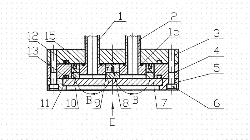
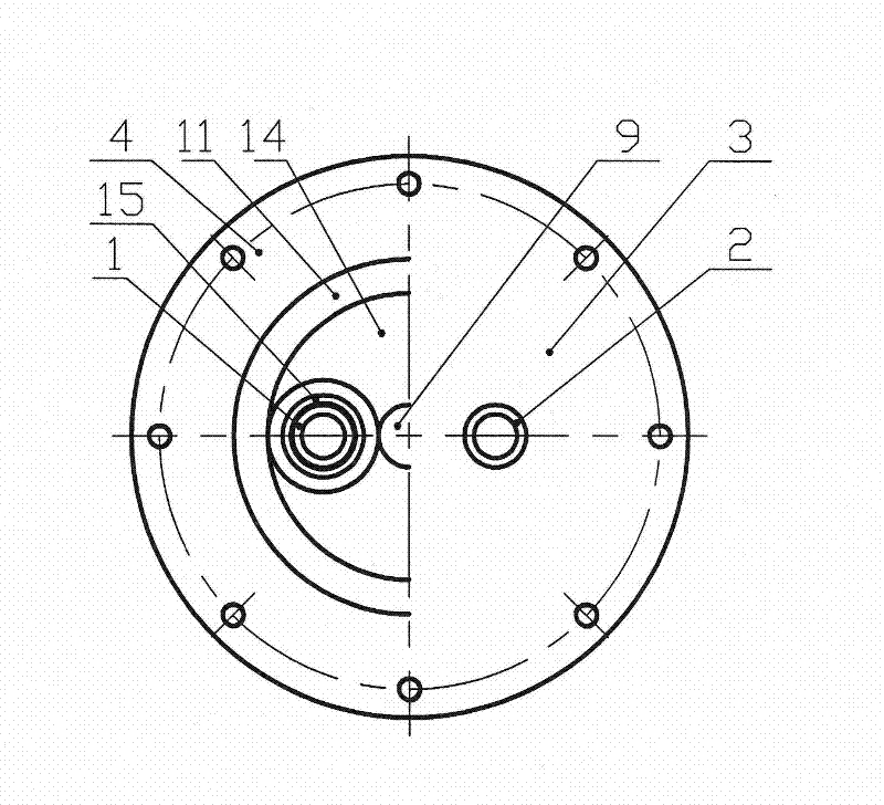
[0021] Such as Figure 5 , 6 As shown, a magnetic-water separation planar magnetron sputtering target includes a cooling water inlet pipe 1, a cooling water outlet pipe 2, a magnetic guide plate 3, a cathode body 4, a target pressure ring 5, a screw 6, a target material 7, and a center The pole shoe 8, the central permanent magnet block 9, the side pole shoe 10, the side permanent magnet block 11 and the lower sealing ring 13, the magnetic guide plate 3, the cathode body 4, the target pressure ring 5 and the target material 7 are all circular. There are through holes through which the cooling water inlet pipe 1 and the cooling water outlet pipe 2 pass through on the magnetic plate 3, which is located on the top of the cathode body 4, the target pressure ring 5 and the target material 7 are located under the cathode body 4, the magnetic guide plate 3, the cathode body 4 and the target pressure ring 5 are fixed by screws 6. The lower sealing ring 13 is located between the catho...
Embodiment 2
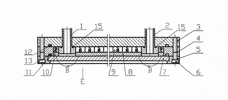
[0023] Such as Figure 7 , 8 Shown: a magnetic-water separation planar magnetron sputtering target, including a cooling water inlet pipe 1, a cooling water outlet pipe 2, a magnetic guide plate 3, a cathode body 4, a target pressure ring 5, a screw 6, a target material 7, and a center Pole shoe 8, central permanent magnet block 9, side pole shoe 10, side permanent magnet block 11 and lower sealing ring 13, magnetic conductive plate 3, cathode body 4, target pressure ring 5 and target material 7 are all rectangular, magnetically conductive There are through holes through which the cooling water inlet pipe 1 and the cooling water outlet pipe 2 pass through on the plate 3, which is located on the top of the cathode body 4, the target pressure ring 5 and the target material 7 are located under the cathode body 4, the magnetically conductive plate 3, the cathode body 4 and the target pressure ring 5 are fixed by screws 6, and the lower sealing ring 13 is located between the cathod...
PUM
 Abstract
Description
Claims
Application Information
 - R&D Engineer
- R&D Manager
- IP Professional
- Industry Leading Data Capabilities
- Powerful AI technology
- Patent DNA Extraction
Browse by: Latest US Patents, China's latest patents, Technical Efficacy Thesaurus, Application Domain, Technology Topic, Popular Technical Reports.
© 2024 PatSnap. All rights reserved.Legal|Privacy policy|Modern Slavery Act Transparency Statement|Sitemap|About US| Contact US: help@patsnap.com


