Diameter reducing machine for small-sized pipe

A technology of reducing machine and pipe body, applied in the direction of the mandrel, etc., can solve the problems of inconsistent wall thickness, increased density, thickened pipe wall, etc., and achieve the effects of reducing production costs, good appearance quality, and reducing consumption

Inactive Publication Date: 2012-01-25
TIANJIN JINBAO MUSICAL INSTR
View PDF0 Cites 0 Cited by
  • Summary
  • Abstract
  • Description
  • Claims
  • Application Information

AI Technical Summary

Problems solved by technology

The disadvantage of this molding method is that the waste of materials is large and the processing technology is complicated.
At present, there is still a mouth forming processing method that uses a brass tube as a blank, and the middle part of the blank is reduced for many times by a diameter reducing machine to form a pipe body. However, the existing diameter reducing machine only shrinks the upper diameter of the blank. The diameter of the part is reduced to the required diameter, but the length of the pipe body remains unchanged, so the density of this part will increase, resulting in thickening of the pipe wall, which will make the wall thickness of different parts of the pipe body inconsistent, resulting in Not only will it affect the appearance quality of the pipe body, but also the consumption of materials is relatively large, resulting in waste of materials and increased production costs

Method used


Image

  • Diameter reducing machine for small-sized pipe
  • Diameter reducing machine for small-sized pipe
  • Diameter reducing machine for small-sized pipe

Examples


Embodiment Construction

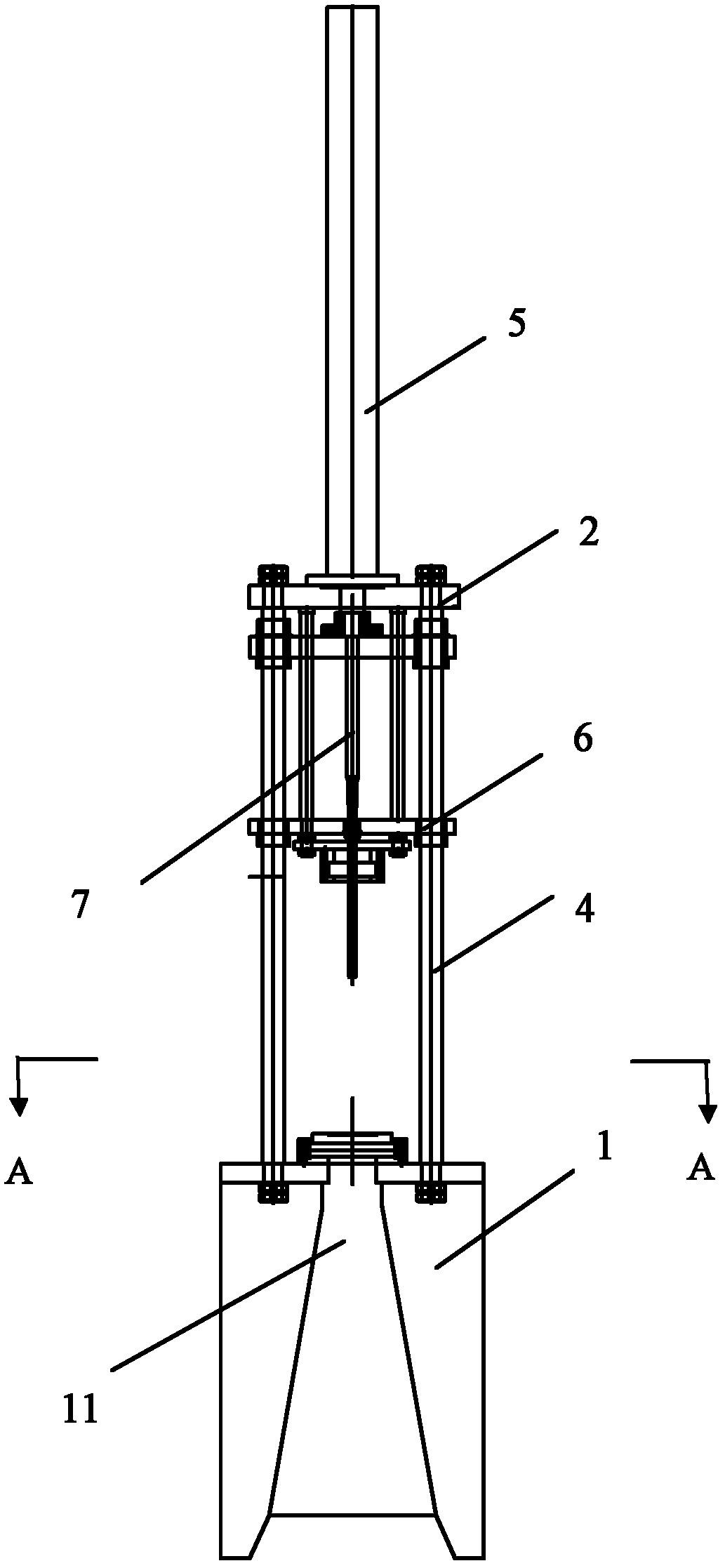
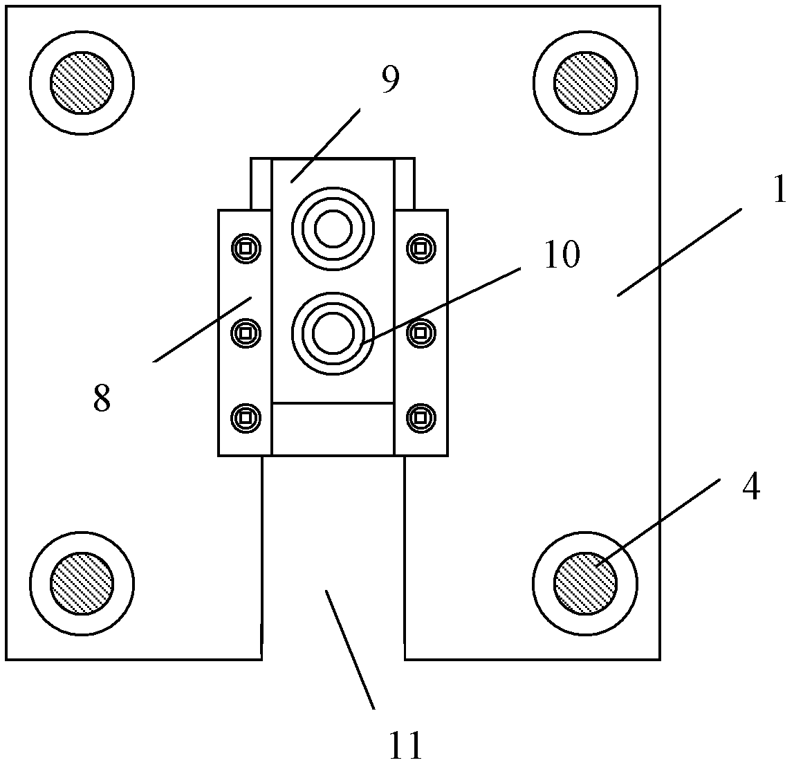
[0011] The small pipe body reducing machine provided by the present invention will be described in detail below in conjunction with the accompanying drawings and specific embodiments.

[0012] Such as Figure 1-Figure 3 As shown, the small pipe body reducing machine provided by the present invention includes a bracket 1, an oil cylinder support frame 2, an oil pump 3, a plurality of guide rails 4, an oil cylinder 5, a stripper plate 6, a mandrel 7, two bases 8, and a slide plate 9 and a reducing sleeve 10; wherein the support 1 is arranged on the ground, and an opening 11 is formed from the center part to the front; the oil pump 3 is installed on the rear surface of the support 1, and its inlet end is connected with the hydraulic system through an oil pipe; The root guide rails 4 are vertically installed on the surface of the support 1 outside the opening 11, and the top surface is provided with an oil cylinder support frame 2; the oil cylinder 5 is vertically installed on the...


PUM


Abstract

The invention provides a diameter reducing machine for a small-sized pipe, which comprises a bracket, an oil cylinder support frame, an oil pump, a plurality of guide rails, an oil cylinder, a material returning plate, a mandrel, two pedestals, a sliding plate and a diameter reducing sleeve. The bracket is arranged on the ground; the oil pump is installed at the back part of the bracket; the plurality of guide rails are vertically installed on the surface of the bracket and the oil cylinder support frame is arranged on the top surface of the bracket; the oil cylinder is vertically installed on the oil cylinder support frame; the upper end of the mandrel is connected with the lower end of a piston rod on the oil cylinder; the outer part of the material returning plate is connected to the plurality of guide rails in a sliding way and the middle part of the material returning plate is connected with the middle part of the mandrel; the pedestals are installed on the surface of the bracket; the sliding plate is horizontally inserted into grooves on the pedestals; and the diameter reducing sleeve is embedded into the sliding plate. According to the diameter reducing machine for the small-sized pipe, provided by the invention, the partial diameter of the pipe is reduced by utilizing the match between the mandrel and the diameter reducing sleeve and the length of the part is lengthened at the same time; and as the thickness of the diameter reducing part is the same as the original thickness of the pipe, not only the produced product good appearance quality is good, but also the use amount of materials is reduced, so that the production cost can be reduced.

Description

technical field [0001] The invention belongs to the technical field of pipe material processing, and in particular relates to a small pipe diameter reducing machine. Background technique [0002] The trumpet is an ancient high-pitched brass instrument. It is mainly composed of a mouthpiece, a tube body and a mechanism. The tube body is in the shape of a slender horn; Performances of baroque music, classical music, military music and jazz, etc. At present, a commonly used method for forming small pipes is to first cut the brass plate into the required plane size of the pipe, and then bend the two sides along the circumferential direction until the two sides are butted and then contact each other. The two sides are then welded together and the welds are ground smooth to form the pipe body. The disadvantage of this molding method is that the waste of materials is large and the processing technology is complicated. At present, there is still a bell mouth forming processing me...

Claims


Application Information

Patent Timeline
IPC IPC(8): B21C1/24B21C3/16
Inventor 李宗瑞
Owner TIANJIN JINBAO MUSICAL INSTR
Why Eureka
Try Eureka