Locking structure of detachable device and portable mobile terminal
A technology for locking structures and devices, applied in the field of electronics, can solve problems such as detachable devices coming out, and achieve the effect of good appearance quality
- Summary
- Abstract
- Description
- Claims
- Application Information
AI Technical Summary
Problems solved by technology
Method used
Image

Examples
Embodiment 1
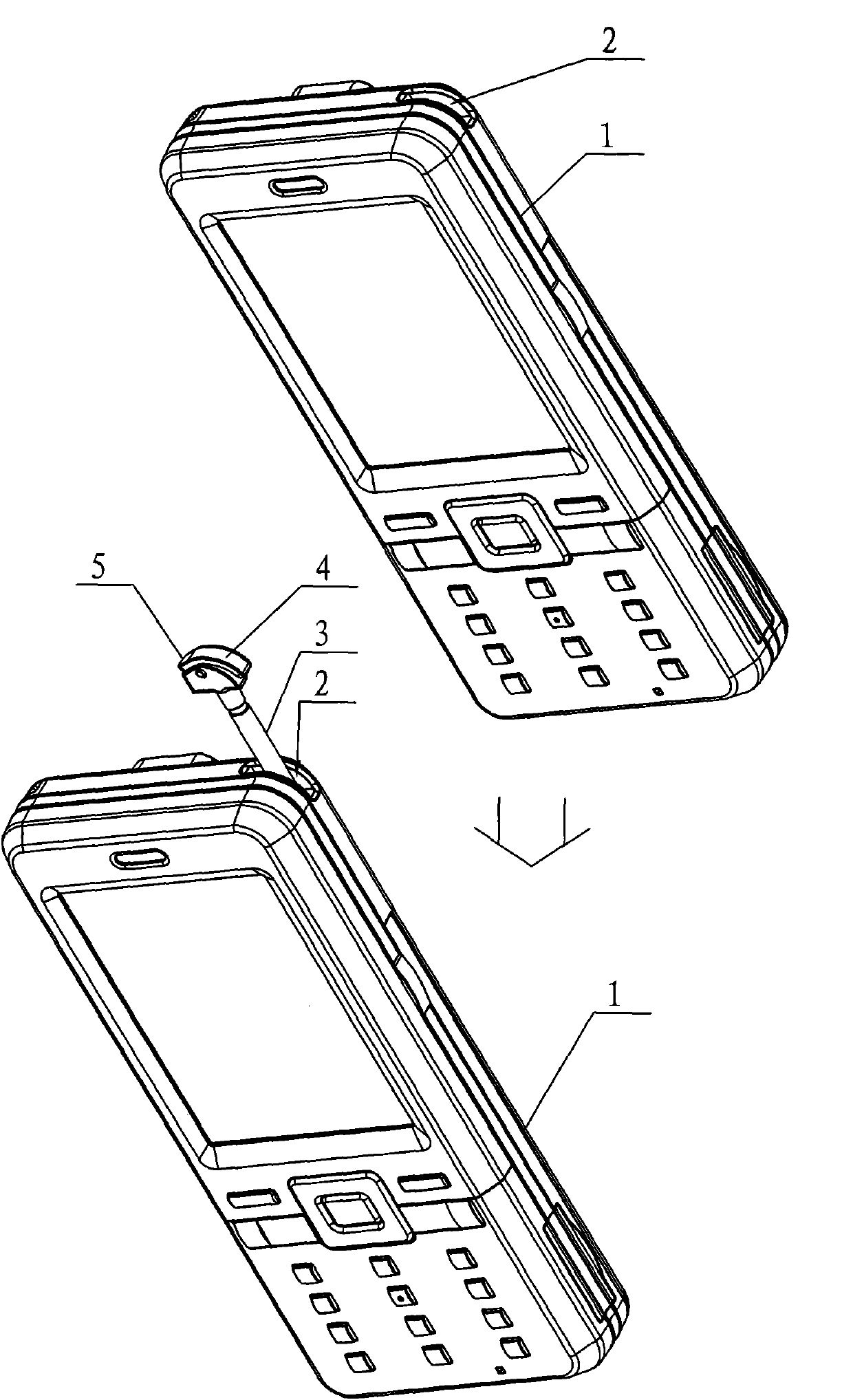
[0033] Such as figure 1 As shown, the locking structure of the detachable device provided by the embodiment of the present invention includes such as figure 1 The shown casing 1 and the installation hole 2 opened on the casing 1, wherein:
[0034] The detachable device 3 is plugged into the installation hole 2 and is detachably connected to the casing 1;
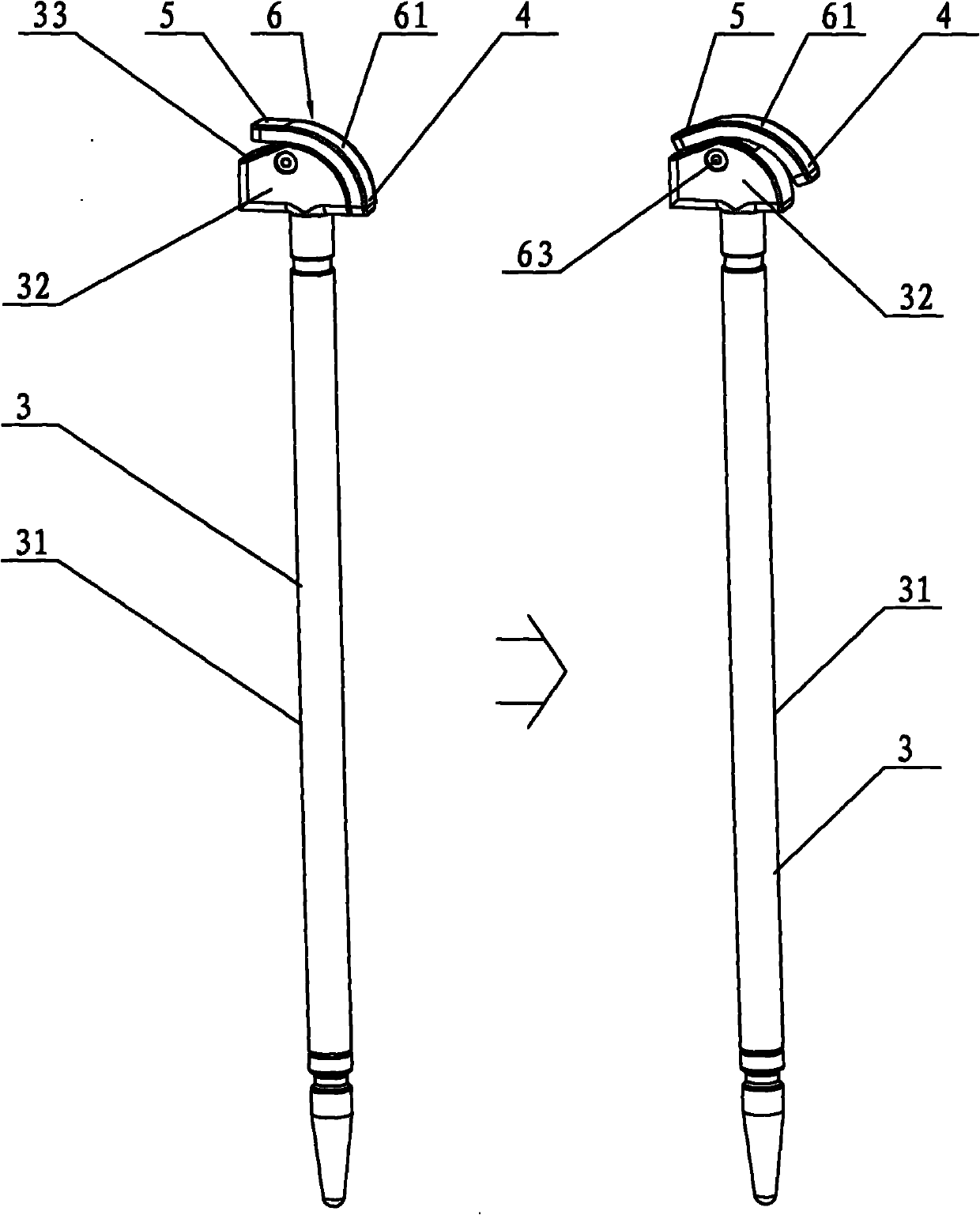
[0035] The side of the detachable device 3 away from the casing 1 is connected as figure 2 The handle part 4 is shown, and the handle part 4 is used to remove the detachable device 3 from such as figure 1 Pull it out from the mounting hole 2 shown;
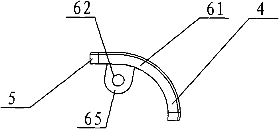
[0036] The side of the detachable device 3 away from the inside of the casing 1 is also connected with a pressing part 5, the pressing part 5 and the handle part 4, and the detachable device 3 are provided with a handle trigger structure 6, when the pressing part 5 is pressed, the handle The trigger structure 6 will cause the handle part 4 to protrude from the mounting hole...
Embodiment 2
[0059] Such as Figure 7 As shown, this embodiment is basically the same as Embodiment 1, and the difference is that in this embodiment, the handle portion 4 is connected to the detachable device 3, and the elastic locking structure 7 includes a locking structure 71 and an elastic structure 72, wherein:
[0060] The locking structure 71 includes a first buckle or first groove 710 provided on the detachable device 3 and a second groove or second buckle 711 provided on the casing 1, the detachable device 3 and the casing 1 pass through The matching structure formed by the first buckle and the second groove and / or the first groove 710 and the second buckle 711 is detachably connected;
[0061] The elastic structure 72 is arranged on the handle part 4 and the detachable device 3. When the handle part 4 is pressed down, the handle part 4 will trigger the elastic structure 72, and the triggered elastic structure 72 will exert elastic force on the handle part 4, so that The handle p...
Embodiment 3
[0067] Such as Figure 8 As shown, this embodiment is basically the same as Embodiment 2, and the difference is that in this embodiment, the elastic structure 72 is arranged on the detachable device 3 and the casing 1, and when the handle part 4 is pressed, the detachable device 3 is far away from The part of the handle part 4 will trigger the elastic structure 72. When the handle part 4 is pressed and then the handle part 4 is released, the triggered elastic structure 72 will exert elastic force on the detachable device 3, so that the handle part 4 is released from the mounting hole. 2 protrudes outside the casing 1.
[0068] Similar to Embodiment 2, the elastic structure 72 in this embodiment can be used between the button of the automatic ballpoint pen and the shell of the automatic ballpoint pen, or between the button of the automatic pencil and the shell of the automatic pencil, or between the button of the water dispenser and the shell of the water dispenser. The elasti...
PUM
 Abstract
Description
Claims
Application Information
 - R&D
- Intellectual Property
- Life Sciences
- Materials
- Tech Scout
- Unparalleled Data Quality
- Higher Quality Content
- 60% Fewer Hallucinations
Browse by: Latest US Patents, China's latest patents, Technical Efficacy Thesaurus, Application Domain, Technology Topic, Popular Technical Reports.
© 2025 PatSnap. All rights reserved.Legal|Privacy policy|Modern Slavery Act Transparency Statement|Sitemap|About US| Contact US: help@patsnap.com