
Refrigeration coaxial light-emitting pipe core

A technology of coaxial light and emission tubes, applied in the coupling of optical waveguides, etc., can solve problems such as signal distortion, restrictions on the installation of heat sinks, and discontinuous impedance of the modulation signal feed-in circuit

Inactive Publication Date: 2012-01-11
SHENZHEN NEOPHOTONICS TECH
View PDF11 Cites 14 Cited by
  • Summary
  • Abstract
  • Description
  • Claims
  • Application Information

AI Technical Summary

Problems solved by technology

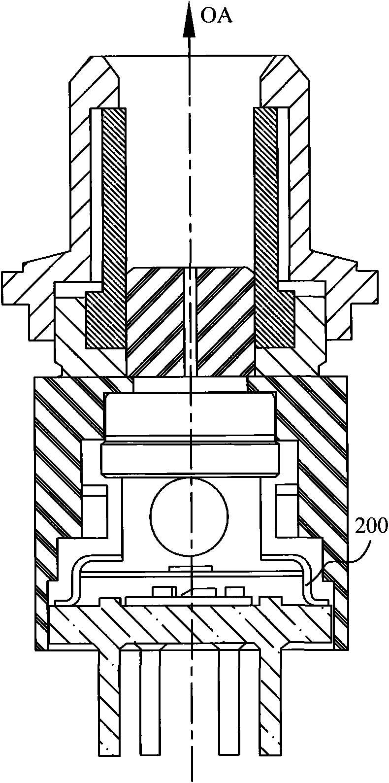
In this structure, the laser chip 201 is mounted horizontally on the carrier 205, causing the optical axis of the laser chip 201 to be located in the horizontal direction and perpendicular to the direction of the optical axis OA of the external optical fiber adapter (also the central axis of the TO socket 207). 204 to rotate the optical axis of the laser chip 201 to the direction of the optical axis OA of the fiber optic adapter, the manufacturing process is complicated and the cost is high
The modulation signal of the laser is fed in through the connection between the carrier 205 and the pin 209 at the bottom of the tube base 207 using a conductive wire 210 by pressure welding. This connection method causes the modulation signal feed-in circuit to have a serious impedance discontinuity problem, especially in The signal will be severely distorted when transmitting high-speed modulation signals above 2.5Gb / s
In addition, the cooler 206 is mounted horizontally on the TO tube base 207, and most of the heat is conducted out through the bottom of the tube base 207. In the application of the optical module, since there are multiple pins 209 distributed at the bottom of the tube base 207, the pins must be directly Soldering or soldering to the circuit board of the optical module through the flexible circuit board limits the installation of the heat sink. At the same time, the heat dissipation area at the bottom is small and the heat dissipation efficiency is low. This design cannot achieve the purpose of efficient heat dissipation and cannot effectively play the role of the cooler 206 effect, thereby limiting the temperature application range of the entire light emitting component

Method used


Image

  • Refrigeration coaxial light-emitting pipe core
  • Refrigeration coaxial light-emitting pipe core
  • Refrigeration coaxial light-emitting pipe core

Examples


Embodiment Construction

[0021] The preferred embodiment of the present invention will be described in detail below in conjunction with the accompanying drawings.

[0022] like Figure 5 A cooling coaxial light emitting tube core includes a TO tube shell 10 and a sealed tube cap 50 with a light window. The tube cap can be a flat window tube cap, or it can be provided with a ball lens or other aspheric The tube cap of the lens is selected according to the design of the coupling optical path, and the surface of the light window is coated with an anti-reflection film to reduce the influence of reflected light on the laser. like Image 6 The illustrated TO package 10 includes a package base 11 and a laser mounting sleeve 12 sealedly connected thereto. The material may be copper or other materials with good thermal conductivity. When the materials of the laser mounting sleeve 12 and the sealing cap 50 are different When matching, it also includes a gold-plated metal ring 40 through which the sealing tube...


PUM


Abstract

The invention provides a refrigeration coaxial light-emitting pipe core, which comprises a TO (transmission optical) pipe shell and a sealing pipe cap with a light window. The TO pipe shell comprises a pipe shell base and a laser mounting sleeve connected with the pipe shell base in a sealing way, the pipe shell base is provided with a plurality of pins electrically connected with an external system, the inner sidewall of the laser mounting sleeve is provided with a mounting platform, a heat dissipating surface of a refrigerator is arranged on the surface of the mounting platform, a refrigeration surface of the refrigerator is used for the arrangement of a laser carrier, the surface of the laser is provided with an electro-absorption modulated n laser chip, a thermistor and a backlight detector, and the light-emitting optical axis of the laser chip is arranged coaxial with the central axis OA of the TO pipe shell and is output by the light window of the sealing pipe cap. Heat dissipation of the whole device is achieved by the laser mounting sleeve instead of the base of the traditional TO pipe shell, and the problem of laser cooling is solved. The pipe core with the structure is coupled with an external optical element of the TO pipe shell to manufacture the light-emitting component with the appearance complying with multi-source agreements XMD (Xilinx microprocessor debugger) for small devices of 10 Gb / s.

Description

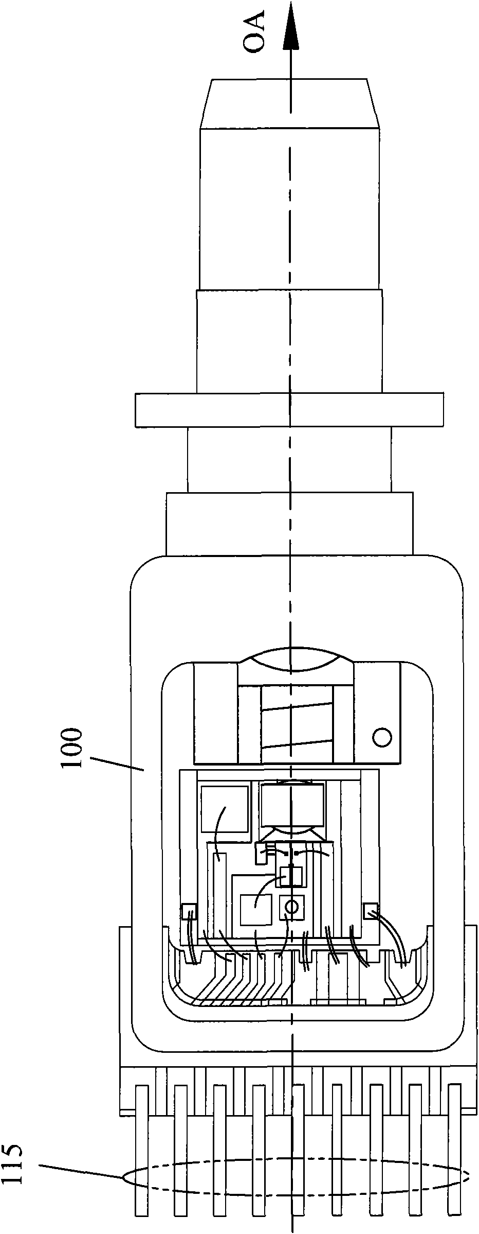
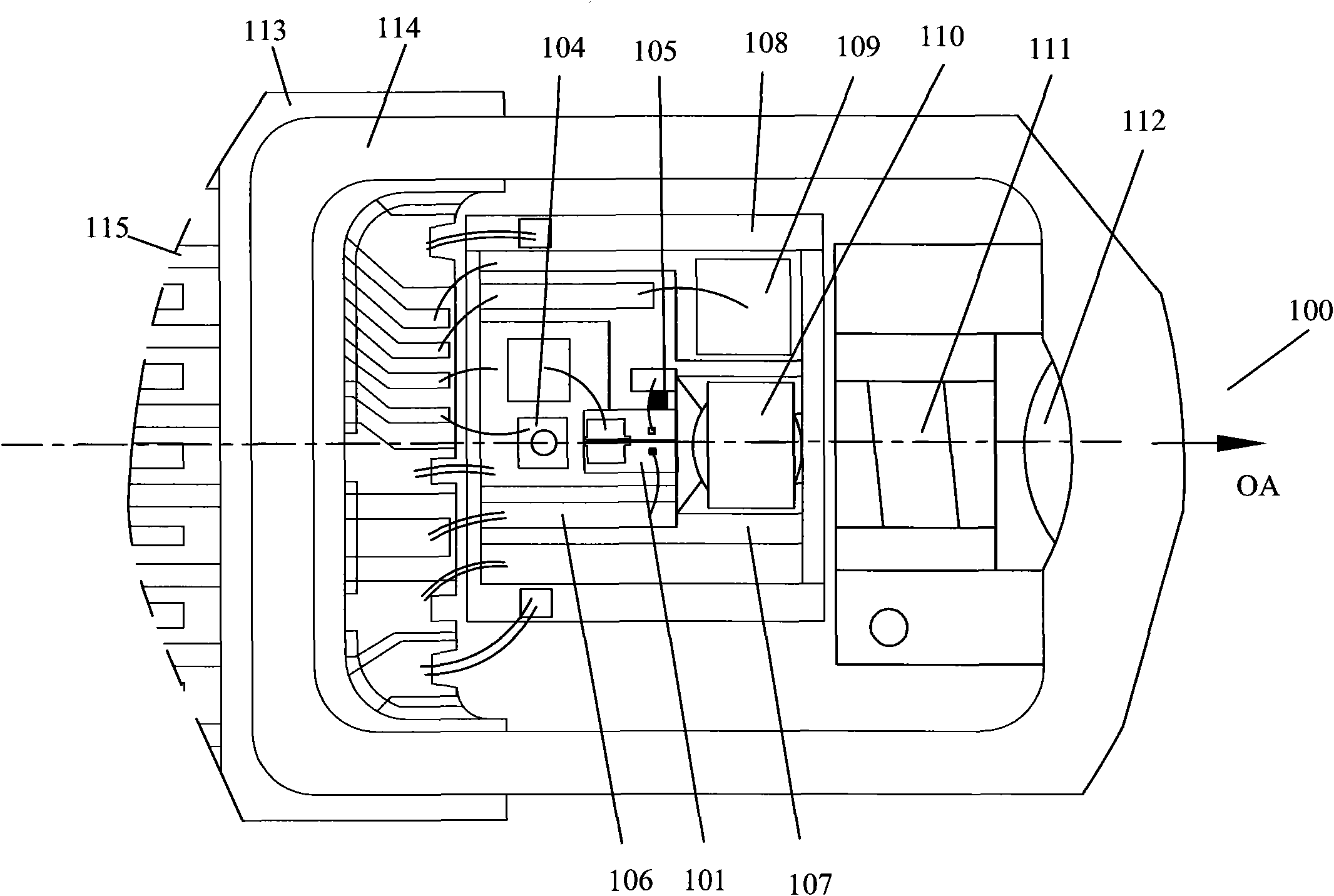
technical field [0001] The invention relates to a light emitting tube core for an optical communication system, in particular to a cooling coaxial light emitting tube core. Background technique [0002] There are two types of light emission dies with cooling in optical communication systems, one such as figure 1 The Chinese invention patent application number shown is CN200510007732.4, which is used in the surface mount type light emitting component described in figure 2 The light emitting die 100 shown is composed of an externally modulated laser chip 101, a backlight detector 104, a silicon optical bench 107 with a matching resistor 105 and a microstrip line 106, a thermoelectric cooler 108, a thermistor 109. Components such as a collimating lens 110, an optical isolator 111, and a focusing lens 112 are assembled in a square metal shell 114 with a multilayer ceramic RF signal feed-in interface 113, and the lead wires 115 are horizontally arranged in the square metal shel...

Claims


Application Information

Patent Timeline
IPC IPC(8): G02B6/42
Inventor 梁泽刘恭志镇磊
Owner SHENZHEN NEOPHOTONICS TECH
Learn More