
A two-stage air-water combined cooling scraper type cold slag conveyor

A combined cooling and slag conveying machine technology, applied in lighting and heating equipment, fluidized bed combustion equipment, combustion methods, etc., can solve problems such as difficult heat recovery, complex operation control, and many mechanical structure failures, so as to improve economic benefits , The system is simple and reliable, and the cooling effect is good

Active Publication Date: 2011-12-21
HUANENG CLEAN ENERGY RES INST
View PDF9 Cites 4 Cited by
  • Summary
  • Abstract
  • Description
  • Claims
  • Application Information

AI Technical Summary

Problems solved by technology

[0003] Although the water-cooled drum type slag cooler has the advantages of relatively simple control and strong adaptability to particle size, it has the following disadvantages: 1) relatively low heat transfer coefficient, 2) relatively many mechanical structural failures, 3) for 300MW grade cycle As far as the fluidized bed boiler is concerned, when condensed water is used as the cooling medium, its pressure is as high as 3.0-3.5MPa, which puts forward higher requirements for the double-layer sealing sleeve and the water inlet and outlet rotary joints, which makes the rotary joints prone to water leakage 4) It is difficult to recover all the heat
However, the slag cooler has the disadvantages of difficult slag feeding control, poor particle size adaptability, complicated operation control, relatively high failure rate, etc., and it is difficult to meet the needs of reliable operation of boiler units.

Method used


Image

  • A two-stage air-water combined cooling scraper type cold slag conveyor
  • A two-stage air-water combined cooling scraper type cold slag conveyor
  • A two-stage air-water combined cooling scraper type cold slag conveyor

Examples


Embodiment Construction

[0025] The present invention will be described in more detail below in conjunction with the accompanying drawings and specific embodiments.

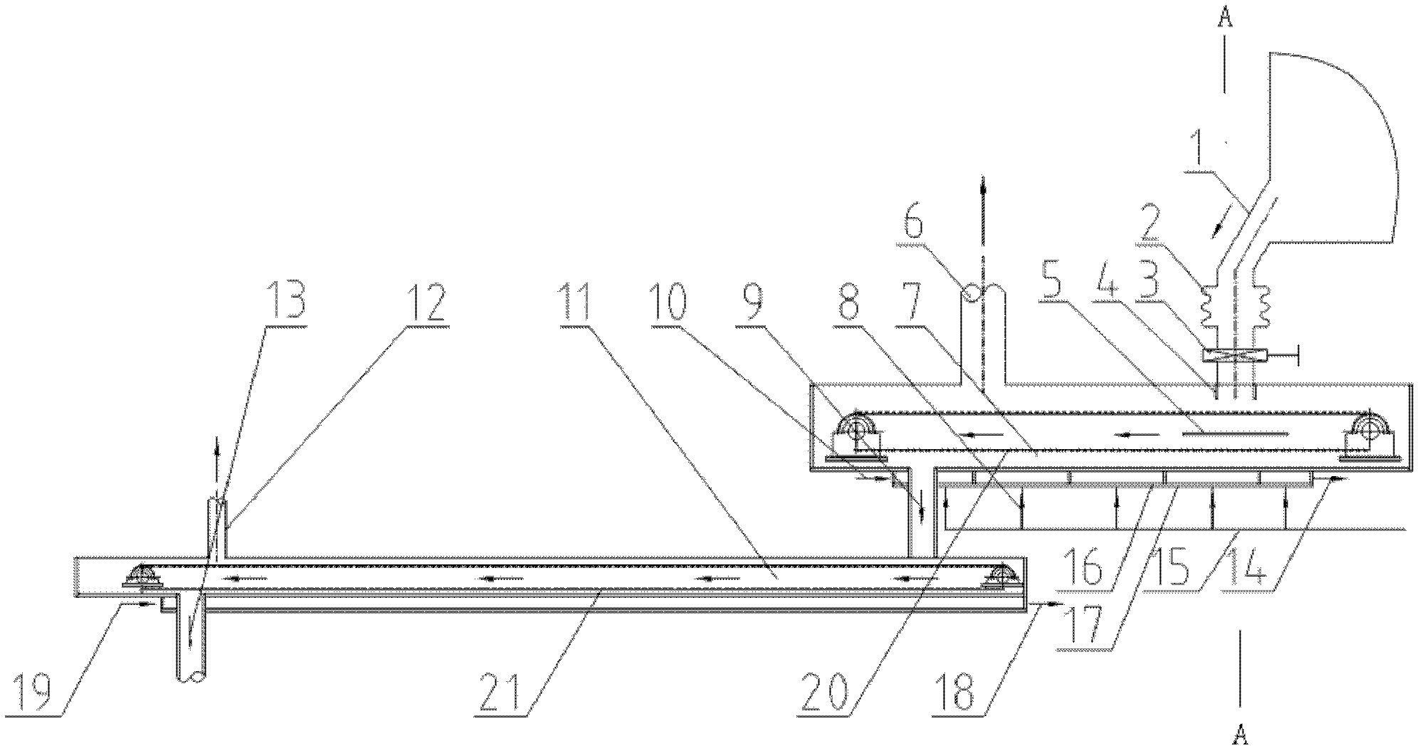
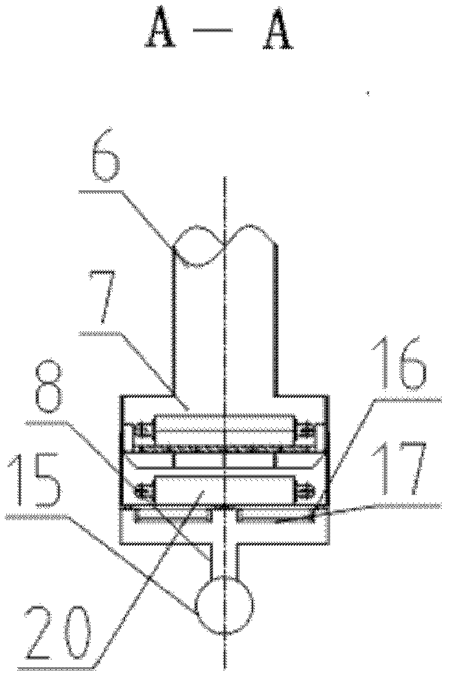
[0026] Such as figure 1 , figure 2 As shown, a two-stage air-water combined cooling scraper type cold slag conveyor of the present invention includes a primary slag cooler 7 with an inlet at the upper front end and an outlet at the lower rear end, and the discharge temperature of the circulating fluidized bed boiler is about The bottom slag at 900°C enters the inlet of the primary slag cooler 7 through the slag discharge pipe 1 of the circulating fluidized bed boiler, the compensator 2 and the grate combination valve 3, and the material guide pipe 4 and sealing The plate 5 realizes the sealing of the high-temperature flue gas in the furnace, and prevents a large amount of hot flue gas from entering the primary slag cooler 7. The lower part of the primary slag cooler 7 is provided with an air distribution plate 16 and a cooling air cham...


PUM


Abstract

The invention relates to a two-stage wind-water joint cooling scraper-type cold slag conveyer which comprises a primary slag cooler; an inlet of the primary slag cooler is communicated with an outlet of a circulating fluidized bed boiler slag discharge pipe; a primary slag cooler scraper is arranged at the middle lower part in the primary slag cooler; the cold slag conveyer also comprises a secondary slag cooler; the inlet of the secondary slag cooler is communicated with the outlet of the primary slag cooler; a secondary slag cooler scraper is arranged at the middle lower part in the secondary slag cooler, a cooling water heating surface is arranged below the secondary slag cooler, and a secondary slag cooler discharge pipe is arranged below the rear part of the secondary slag cooler; bottom flag enters a wind-water joint cooling primary slag cooler; when being cooled, the bottom slag is conveyed by the primary slag cooler scraper; hot air after heat exchange returns to a hearth through an air return pipe; the primarily cooled bottom slag enters the secondary slag cooler; a cooling water jacket further cools the bottom slag and sends the bottom slag to follow-up slag conveying equipment; and the cold slag conveyer has a good slag cooling effect, is not restricted by the grain size of the bottom slag, integrates slag cooling and slag conveying, so that the system is simpler and more reliable.

Description

technical field [0001] The invention relates to the technical field of circulating fluidized bed boiler bottom slag cooling and conveying, in particular to a two-stage air-water combined cooling scraper type cold slag conveyor. Background technique [0002] The emission control and cooling of the bottom slag are the prominent problems plaguing circulating fluidized bed boiler power plants at present, which directly affect the safe and stable operation of the entire unit. Due to problems such as slagging, wear, slagging control failure, failure to achieve the expected cooling effect and low output, the failure of the slag cooler caused great economic losses to the power plant. At present, there are mainly two types of slag coolers for circulating fluidized bed boilers with a wide range of applications: water-cooled drum type and wind-water combined fluidized bed type. [0003] Although the water-cooled drum type slag cooler has the advantages of relatively simple control and...

Claims


Application Information

Patent Timeline
Patent Type & Authority Applications(China)
IPC IPC(8): F23C10/24
Inventor 郭涛
Owner HUANENG CLEAN ENERGY RES INST
Learn More