
Water-assisted molding process and constant pressure water-assisted injection molding equipment

An injection molding, water-assisted technology, applied in the field of injection molding technology and equipment, can solve the problems of injection water pressure loss impact, long system response time, and rapid melt cooling, etc., to solve the pressure loss impact, which is beneficial to cooling, The effect of high specific heat capacity

Inactive Publication Date: 2011-12-21
韩国海 +1
View PDF2 Cites 17 Cited by
  • Summary
  • Abstract
  • Description
  • Claims
  • Application Information

AI Technical Summary

Problems solved by technology

[0004] The purpose of the present invention is to provide a water-assisted molding process and constant-pressure water-assisted injection molding equipment. The technical problems to be solved are the problems of excessive cooling and solidification of the melt in the existing water-assisted molding process, and the instantaneous pressure loss impact of injected water. As well as problems in the existing water-assisted molding equipment such as long system response time, constant injection water volume and pressure, uncontrollable flow rate, sealing and discharge of injection water, unnecessary closed-loop precise control of water temperature, etc., to achieve smooth water injection and pressure maintenance, and improve Improve the quality of plastic parts, reduce product development and production costs

Method used


Image

  • Water-assisted molding process and constant pressure water-assisted injection molding equipment
  • Water-assisted molding process and constant pressure water-assisted injection molding equipment
  • Water-assisted molding process and constant pressure water-assisted injection molding equipment

Examples


Embodiment Construction

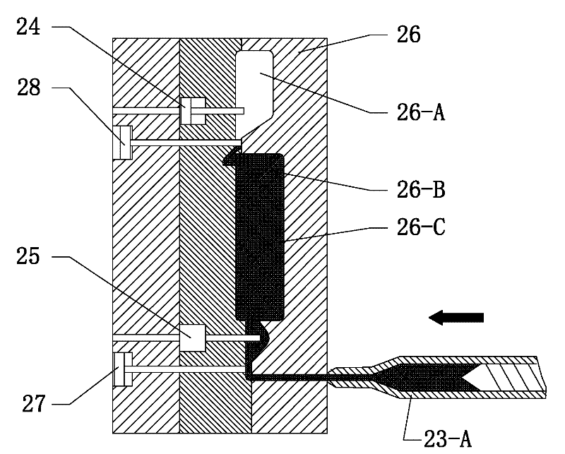
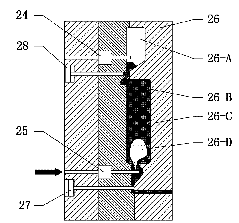
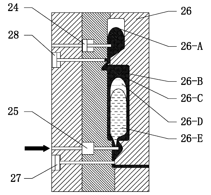
[0036] The present invention will be described in further detail below in conjunction with the accompanying drawings and embodiments. exist Figure 1-12 Among them, each serial number indicates: 1. High-pressure water source, 2. High-pressure nitrogen source, 3. Compressed air source, 4. High-pressure water stop valve, 5. High-pressure nitrogen stop valve, 6. Compressed air stop valve, 7. High-pressure water filter , 8. High pressure nitrogen filter, 9. Compressed air filter, 10. Water injection accumulator, 11. Water injection high pressure solenoid valve, 12. Flow regulating solenoid valve, 13. Gas injection high pressure solenoid valve, 14. Gas injection solenoid valve , 15. High-pressure electric gas valve, 16. First one-way valve, 17. High-pressure electric water valve, 18. Pressure sensor, 19. Program controller, 20. Step-down solenoid valve, 21. Filter, 22. Water tank, 23. Injection molding machine controller, 23-A. Injection mechanism of injection molding machine, 24....


PUM


Abstract

The invention discloses a water-assisted molding process and constant pressure water-assisted injection molding equipment and aims to realize stable water injection and pressure maintenance and improve the quality of plastic parts. The equipment comprises an injection molding machine controller, a hydraulic control telescopic gas needle and a water needle, wherein the water needle is connected with a gas injection pressure closed-loop control circuit, a water injection pressure closed-loop control circuit and a depressurization closed-loop control circuit respectively; and the hydraulic control telescopic gas needle is connected with a compressed air drainage unit. The water-assisted molding process comprises the following steps of: a, injecting a plastic melt into a die cavity; b, injecting a little nitrogen into the plastic melt; c, injecting high-pressure water into the rear part of the nitrogen; d, injecting the high-pressure water into the die cavity and maintaining the pressure;e, after cooling, curing and molding, draining the injected water and reducing the pressure; f, draining the injected water completely; g, ejecting a plastic part; and h, entering the next period. Compared with the prior art, the equipment is provided with a gas pressure supercharger and a water pressure generating device to fulfill the aims of realizing stable water injection and pressure maintenance and reducing the product development and production cost.

Description

technical field [0001] The invention relates to an injection molding process and equipment, in particular to a gas-assisted molding technology, combined with the characteristics of water-assisted molding, using gas and water as the medium, and automatically controlling the pressure and flow of water injected into the plastic part after pressurization. Water-assisted molding process for hollow products made of plastic and constant-pressure water-assisted injection molding equipment. Background technique [0002] Over the years, people have been exploring and improving the molding and processing technology of plastic products. In the 1970s, the gas-assisted molding technology developed for the purpose of reducing warpage, avoiding dents and reducing raw material consumption has been proposed and gradually applied. We have also done some research in this field, such as invention patents: ZL: 200510121110.4. In recent years, due to some deficiencies exposed in the use of gas-a...

Claims


Application Information

Patent Timeline
IPC IPC(8): B29C45/03B29C45/57B29C45/77B29C45/17
Inventor 韩国海何萍
Owner 韩国海
Learn More