
Junction box of solar photovoltaic module

A solar photovoltaic and junction box technology, which is applied in the field of solar photovoltaic module junction boxes, can solve the problems of shortening the service life of junction boxes, aging cracks, poor heat dissipation of junction boxes, etc., and achieves improved stability and photoelectric conversion efficiency, high voltage resistance and electrical conductivity The effect of strengthening capacity and facilitating automatic production and processing

Inactive Publication Date: 2011-11-30
崔鹏 +1
View PDF5 Cites 8 Cited by
  • Summary
  • Abstract
  • Description
  • Claims
  • Application Information

AI Technical Summary

Problems solved by technology

[0005] 2. Large volume and poor heat dissipation performance
[0006] Existing junction boxes are generally equipped with metal terminals, which have poor heat dissipation performance, and there is a cavity inside, which can only dissipate heat through air convection, and the heat dissipation effect is not good. Even if the heat is dissipated by potting glue inside, a relatively ideal effect cannot be achieved; At the same time, considering reasons such as heat dissipation and electrical clearance, the junction box is relatively large in size, which is not only complicated in structure, but also easily damaged during use.
In addition, due to the poor heat dissipation of the junction box, the phenomenon of junction box burning occurs frequently, and even causes great harm to the photovoltaic system.
[0007] 3. Short service life
[0008] After opening the box cover of the existing junction box, the internal components are directly exposed to the air. During use, the metal parts of electrical terminals, diodes, cables and other components are easily corroded and oxidized, and the plastic parts are easy to age, which greatly shortens the wiring time. The life of the box
[0009] 4. Poor current carrying capacity
[0010] In the existing junction box, the diodes between the electrical terminals are usually tubular diodes with small pins and poor current carrying capacity
The bus bar and the input ends of the corresponding electrical terminals are connected by clamping. Although the assembly operation is quick, but because the conductors are connected by wires, the conductive area is small, the contact resistance is large, and the connection is not reliable enough, which is prone to poor contact. , shedding, abnormal discharge, etc.
During use, due to the weak current carrying capacity and high power consumption, the junction box may be broken down or burned under high temperature and high pressure conditions
[0011] 5. Poor waterproof and dustproof performance
Water seepage in the junction box or changes in the electrical clearance will cause adverse effects such as abnormal discharge of components, insulation breakdown, short circuit, etc. during the use of the junction box, causing damage to the junction box and burning, and more likely to burn components connected to the junction box and others. components, causing serious economic losses
For the cable part, sealing nuts are generally used for sealing. During long-term use, the sealing nuts will cause aging and cracking due to improper material selection or impure materials, internal stress release, external force impact, etc. The waterproof and dustproof performance Secondly, for the box body, the existing junction box structure is an upper and lower split structure, the opening area is relatively large, the structural shape is complex, the box cover and the box body are easy to shrink and deform during the injection molding process, and large-area plastic parts The residual internal stress is also relatively large. If it is used in a high temperature and high humidity environment for a long time, the junction box will be more prone to deformation due to uneven thermal expansion, such as box cover warping, bulging, and mouth opening, which will affect the waterproof and dustproof performance.
Moisture, fine impurity particles, etc. will enter the box more easily, and will directly contact the components after entering the box, causing serious safety accidents

Method used


Image

  • Junction box of solar photovoltaic module
  • Junction box of solar photovoltaic module
  • Junction box of solar photovoltaic module

Examples


Embodiment Construction

[0034] Specific embodiments of the present invention will be further described in detail below.

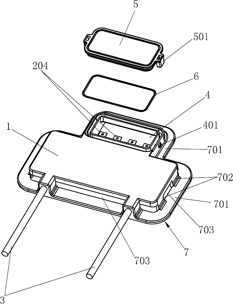
[0035] like Figure 1~5 Shown, the present invention comprises electric part 2, and electric part 2 comprises a group of metal sheets 201 and the diode 202 that is connected between metal sheets 201, and cable 3 connects two sheet metal sheets 201 of electric part 2 both sides, and connection mode can be by The tail ends 205 of the metal sheets 201 on the left and right sides of the electrical part 2 are bent and tightly wrapped around the cable 3. The number of metal sheets 201 and diodes 202 is determined according to different requirements. In this embodiment, the electrical part 2 includes 4 metal sheets 201 and three diodes 201 connected in series between four metal sheets 201, the metal sheet 201 is a copper sheet, the diode 202 is a patch diode, and the metal sheet 201 is extended with an integral heat sink 203, so that the metal sheet 201 As a conductive component, it als...


PUM


Abstract

The invention relates to a junction box of a solar photovoltaic module, which is characterized by comprising an electrical part, wherein the electrical part comprises a group of metal sheets and diodes which are connected among the metal sheets; a cable conductor is connected with the electrical part; the electrical part and one connecting end of the cable conductor are packaged in a body plastically; the front side of the body is provided with a connecting line cavity body which is provided with a sealed cover, and a seal ring is arranged between the sealed cover and the connecting line cavity body; a radiating cavity body is arranged below the body and formed by a mounting edge and a lateral bar, and the lateral bar is connected with the mounting edge and the body; and the front ends of the metal sheets extend out of the body to stretch into the connecting line cavity body so as to form lead ends, and the mounting edge is arranged below the connecting line cavity body in an extended mode. The body, the electrical part, the connecting line cavity body and the radiating cavity body are subjected to the integral injection molding to form an integral body. The technology is simple, the manufacturing cost is low, the volume is small, the radiating performance is good, the current bearing capacity is strong, the waterproof and dustproof performance is good, and the service life is long.

Description

technical field [0001] The invention relates to a solar photovoltaic power generation system component, in particular to an integral injection-molded junction box of a solar photovoltaic module. Background technique [0002] The solar photovoltaic module junction box is an important part of the solar photovoltaic power generation system. It is a connector between the solar cell array formed by the solar cell module and the solar cell charging control device. The existing solar photovoltaic module junction box usually adopts the upper and lower split structure of the box body and the box cover, and there are many components installed in the junction box, which mainly has the following problems: [0003] 1. The process is cumbersome and the manufacturing cost is high. [0004] Due to the large number of parts, a complete junction box needs to be completed through subsequent assembly. The manufacturing, processing and assembly of parts is troublesome, the process is quite cumb...

Claims


Application Information

Patent Timeline
IPC IPC(8): H01L31/048H02S40/34
CPCY02E10/50Y02A30/14
Inventor 施振德
Owner 崔鹏
Learn More