
Preparation method of lithium niobate optical waveguide

A technology of lithium niobate and optical waveguide, which is applied in the direction of optical waveguide light guide, light guide, optics, etc., can solve the problems of poor resistance to photorefractive damage, small size of optical waveguide, and limitation of conversion efficiency, etc., to reduce waveguide transmission loss , good verticality and improved conversion efficiency

Inactive Publication Date: 2011-11-23
HUAZHONG UNIV OF SCI & TECH
View PDF2 Cites 14 Cited by
  • Summary
  • Abstract
  • Description
  • Claims
  • Application Information

AI Technical Summary

Problems solved by technology

[0003] So far, the preparation methods of lithium niobate optical waveguide mainly adopt Ti diffusion method, annealing proton exchange method and liquid phase epitaxial ridge waveguide method, and Ti diffusion lithium niobate optical waveguide (Ti:LiNbO3) has poor resistance to photorefractive damage. Usually need to work above 100°C to reduce photorefractive damage; annealed proton exchange lithium niobate optical waveguide (APE:LiNbO3) is much better than Ti:LiNbO3 in resisting photorefractive damage, but it usually needs to work above 90°C ; Doped with Mg, MgO or Zn, ZnO can reduce photorefractive damage, the corresponding annealed proton exchange optical waveguide (APE:Mg:LiNbO3, APE:MgO:LiNbO3, APE:Zn:LiNbO3, APE:ZnO:LiNbO3) anti-light Refractive damage ability is better than APE:LiNbO3, but it still needs to work at 60°C to further eliminate the influence of photorefractive damage; LiNbO3 optical waveguide (LPE:LiNbO3) prepared by liquid phase epitaxial ridge waveguide method has the advantages of photorefractive resistance The damage ability has been significantly improved, and it can work at room temperature, but the size of the optical waveguide prepared by the liquid phase epitaxial ridge waveguide method is not large, and the conversion efficiency is limited to a certain extent.

Method used


Image

  • Preparation method of lithium niobate optical waveguide
  • Preparation method of lithium niobate optical waveguide

Examples


Embodiment 1

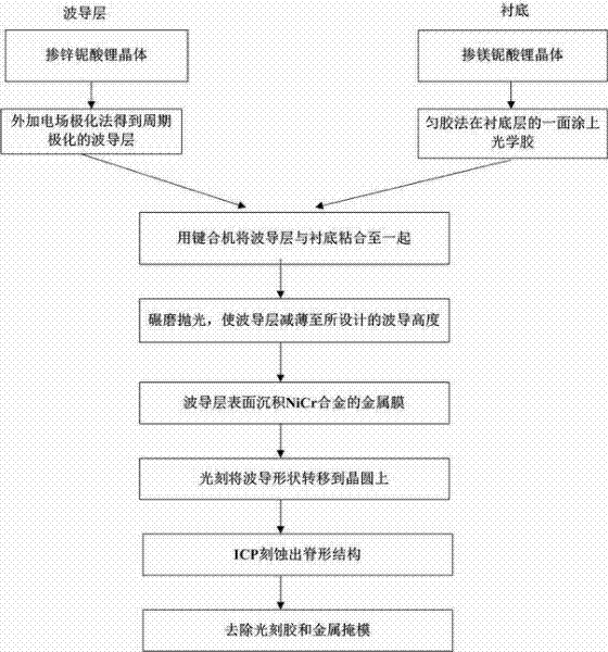
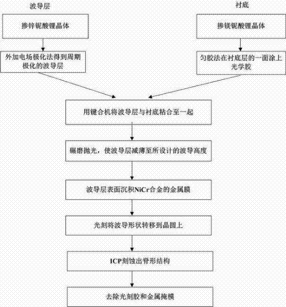
[0025] Embodiment 1 is to prepare a lithium niobate optical waveguide with a ridge waveguide width of 5 μm and a height of 4 μm, such as figure 1 Shown, its preparation method comprises the following steps:

[0026] (1) A zinc-doped z-cut lithium niobate wafer (Zn:LN) is selected as the waveguide layer, and its zinc-doped concentration ranges from 7 to 9 mol%, and 7 mol% is used in this embodiment. The substrate is a magnesium-doped lithium niobate crystal (Mg:LN), and the magnesium-doped concentration ranges from 5 to 9 mol%, and 5 mol% is used in this embodiment.

[0027] (2) Periodically polarize the waveguide layer by using the external electric field polarization method to prepare a periodic domain inversion structure of the waveguide layer; where the polarization period is substituted into the periodic polarization formula Λ by using different wavelengths of refraction indices of zinc-doped lithium niobate 0 =1 / (n p / λ p -n i / λ i -n s / λ s ), where Λ 0 is the po...

Embodiment 2

[0033] Embodiment 2 is to prepare a lithium niobate optical waveguide with a ridge waveguide width of 8 μm and a height of 5 μm, and its preparation method includes the following steps:

[0034] (1) The waveguide layer in the lithium niobate waveguide is selected as magnesium-doped lithium niobate crystal (Mg:LN), the concentration range of magnesium doping is 5-9 mol%, 5 mol% is taken in this embodiment, and the substrate is lithium tantalate crystal (LT).

[0035] (2) Periodically polarize the waveguide layer by using an external electric field polarization method to prepare a periodic domain inversion structure of the waveguide layer; where the polarization period is substituted into the periodic polarization formula Λ by using different wavelengths of magnesium-doped lithium niobate 0 =1 / (n p / λ p -ni / λ i -n s / λ s ), where Λ 0 is the polarization period, let the pump light wavelength λ p =775nm, signal light wavelength λ s =1545nm, idler wavelength λ i =1555nm, ...


PUM


Abstract

The invention provides a preparation method of a lithium niobate optical waveguide. The preparation method of the lithium niobate optical waveguide comprises the steps of: fabricating a periodical domain inversion structure on a doped lithium niobate crystal by adopting an applied electric field polarization method by selecting a zinc-doped or magnesium-doped lithium niobate crystal; bonding the periodical domain inversion structure as a waveguide layer with a lithium niobate substrate or a lithium tantalite substrate through optical cement the refractive index of which is lower than that of the waveguide layer; and etching to obtain a ridge waveguide structure by using an ICP (inductively coupled plasma) dry method to obtain the lithium niobate optical waveguide. The adhesive layer adopted by the invention has a reflective index more approaching that of air, therefore, in the waveguide, the optical field limiting function is stronger, the optical field is distributed symmetrically, and the coupling efficiency of single mode fibers is higher. By adopting adhesive bonding, the requirement on cleanness and roughness of the surface of a wafer is far lower than that of the surface of a directly bonded wafer, thus the preparation method is realized more easily in technology. The lithium niobate optical waveguide prepared by the method has more excellent performance in the aspects of improving the optical field limiting function, reducing the transmission loss of the waveguide, inhibiting the photorefractive effect, reducing the difficulty in manufacturing technology and the like.

Description

technical field [0001] The invention relates to a method for preparing an optical waveguide, in particular to a method for preparing a lithium niobate optical waveguide by using adhesive bonding. Background technique [0002] In recent years, the optical communication industry has gradually stepped out of the downturn, and the research and development of all-optical networks has received more and more attention. In order to build high-speed and large-capacity DWDM and OTDM all-optical networks, ultra-fast, low-noise, easy-to-integrate, and multi-functional all-optical signal processing technology is very important. The second-order and cascaded second-order nonlinear effects in lithium niobate optical waveguides have great application potential in all-optical wavelength conversion, all-optical switches, all-optical logic gates, and all-optical code conversion. s concern. [0003] So far, the preparation methods of lithium niobate optical waveguide mainly adopt Ti diffusion...

Claims


Application Information

Patent Timeline
Patent Type & Authority Applications(China)
IPC IPC(8): G02B6/138G02B6/13
Inventor 孙军强周钰杰冯力群
Owner HUAZHONG UNIV OF SCI & TECH
Learn More